Calibration & Measurement Module for OTKB/OTKBFM Chapter 3: Introduction
TTN030035-D02 Page 4
3.1. Position Calibration
The data acquired from the QPD detector is given in volts. For quantitative force and position measurements it is
necessary to determine the detector responsivity factor. The method used with the OTKBFM-Cal requires a stuck
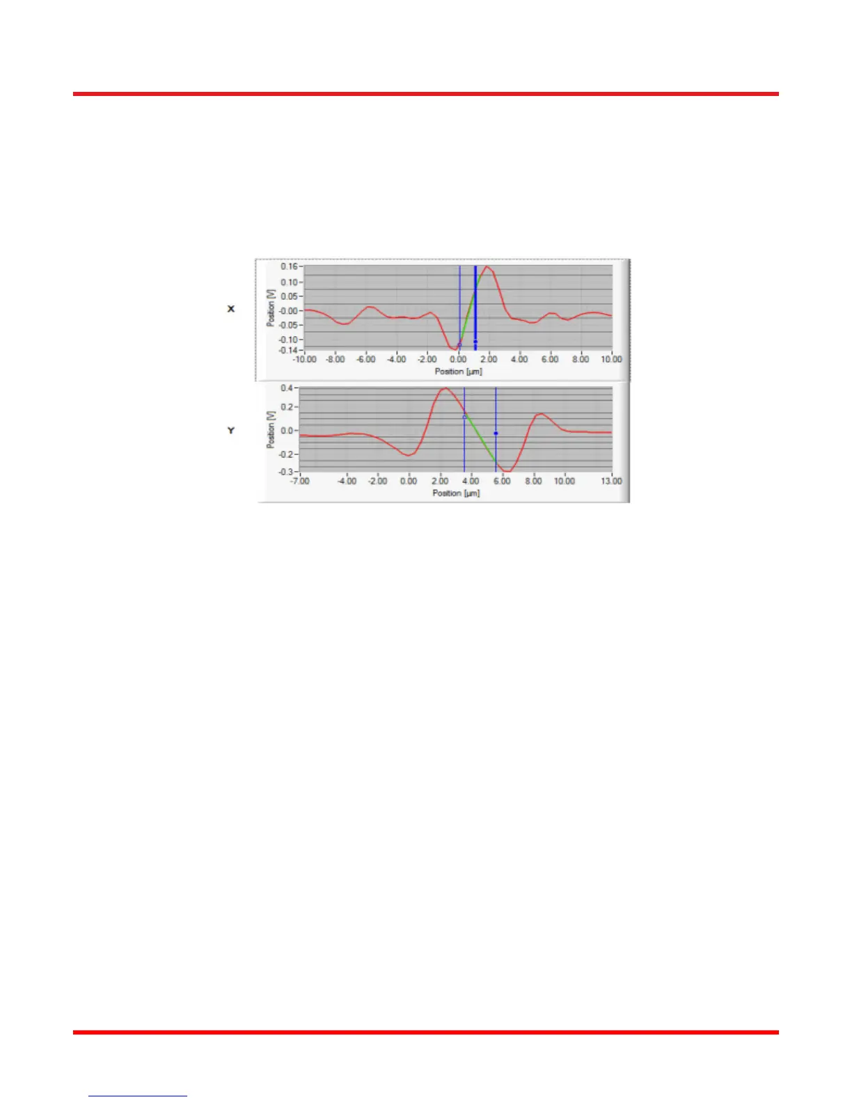
bead to be moved across the location of the trap while recording the detector voltage. Using the sample stage,
steps of known size are used which then allow plotting of the position signal in volts versus the position signal in
microns. When the bead moves across the trap position an S-shaped curved is formed as shown in Figure 2.
Note that the conversion factor only applies if the distance of the trapped particle to the trap center lies within the
linear range.
Figure 2 Typical position calibration curve. QPD voltage data is acquired while a stuck bead is
moved across the focal spot / trap position.