Calibration & Measurement Module for OTKB/OTKBFM Chapter 6: Frequently Asked Questions
Page 15 Rev C, August 2, 2018
4. When I start data tracking in the OTKBFM-CAL software the X,Y,SUM data is zero (0 V)?
a. Check that you have switched on the laser.
b. Make sure the laser beam is aligned to the center of the QPD.
c. Check the connections of the cables from the PSD K-Cube to the OTKBFM-CAL module.
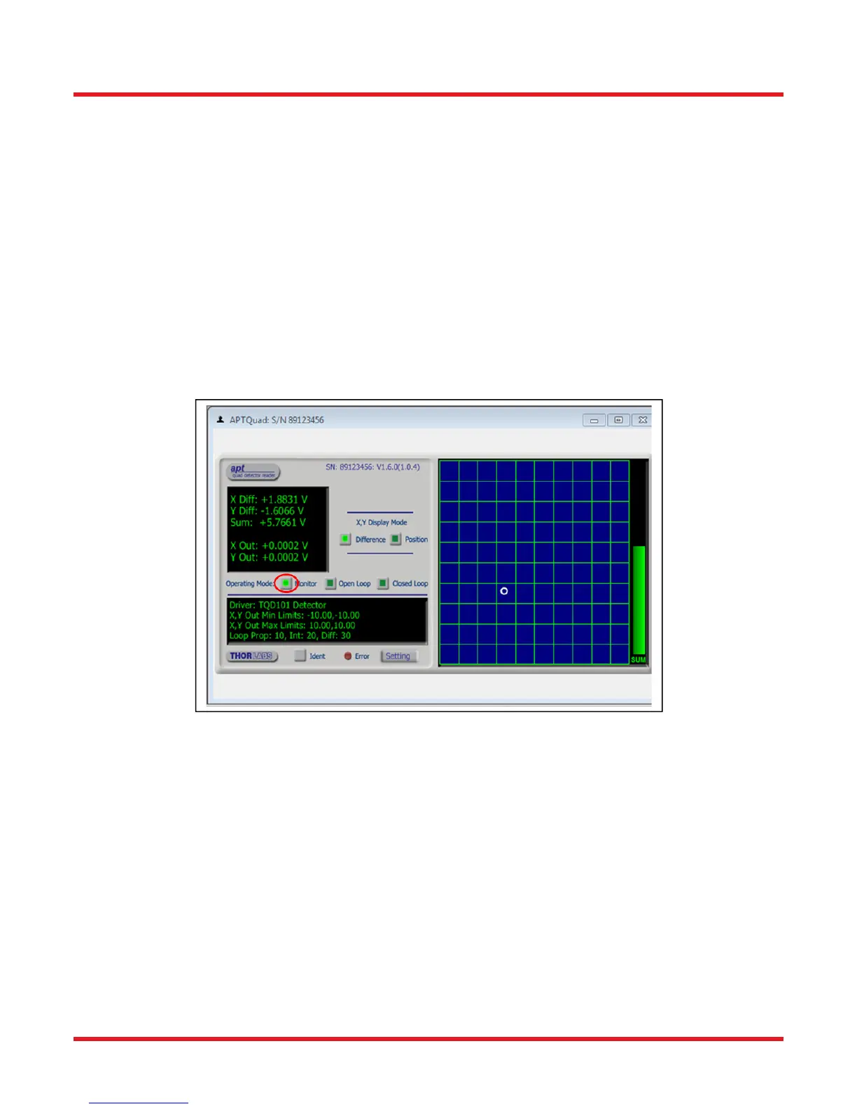
d. Check the PSD K-Cube is set to “Monitor Mode” as shown in Fig.4 . Use the Thorlabs APT User
software to access the panel shown and adjust this setting.
5. When I start data tracking in the OTKBFM-CAL software only the SUM signal changes.
Make sure that the K-Cube controller for the PSD detector is set to “Monitor Mode”. Use the APT User
software to check this setting. See Figure below with the Monitor setting marked by a red circle.
6. Why are there multiple roll off frequencies in the power spectrum plot?
a. You have more than one bead in the optical trap.
 Loading...