4
21LFT25430 Issue 6 PN 2307F Oct 17
SMARTSCAN
MENU OPTIONS SMARTSCAN SENSORS
STATUS LED INDICATOR
DOWNLOAD ALL - Downloads all SmartScan settings into the Smart
programmer.
PROGRAM ALL- Uploads all settings to the SmartScan luminaire.
BUILDING ADDRESS - Identies devices that are within the same system
and forms the boundary for the wireless mesh to prevent adjacent
buildings communicating. The building address can be set between
1-254.
GROUP ADDRESS - The control group, all luminaires with the same
building address and the same group address will work together for
presence detecton and scene control. Up to 254 dierent groups can be
created in one building. The group address can be set between 1-254.
DEVICE ADDRESS- The unique device address within each group. This is
used to identify individual luminaires on the system. The device address
can be set between 1-254.
LINK ADDRESS (TX AND RX) - The link address allows presence
detection signals to be transmitted between dierent groups of
luminaires. Each group can be set to transmit or receive an independent
link address enabling occupancy in one area to keep another linked
un-occupied area illuminated. The link transmit (TX) or link receive (RX)
addresses can be set between 1-254.
READ UNIQUE DEVICE ID (UDID) - When a luminaire is connected to
the SmartScan Gateway via the mesh network it is issued with a unique
device ID number. This is used by the system to track luminaires if group
or device addresses are changed by the user. The ‘UDID’ can be between
1 and 500.
RF TRANSMIT - All SmartScan luminaires are delivered with RF disabled.
RF must be enabled after addresses are set to allow communication.
RADIO LED - Radio trac indication is turned o by default to avoid user
nuisance. It can be enabled for commissioning and testing purpose.
JOIN RADIO NETWORK - Sends a join request from the luminaire to the
SmartScan Gateway. Once accepted the Gateway will issue a UDID and
request luminaire status. Note: wait 60 seconds between re-issuing join
requests.
SEND PING REQUEST - Sends a ping request to the SmartScan Gateway
to check radio communication.
LEAVE RADIO NETWORK - Send a message to the SmartScan Gateway
to remove the luminaire from the network. Once accepted the UDID is
removed from the luminaire. Note: If you remove a luminaire without
leaving the radio network the system will report the unit as faulty.
RADIO MODULE PLUGGED IN - Checks that the Smart sensor has the
SmartScan radio module connected. The answer is either Y (Yes) or N (No).
DALI TUNNEL- Enables or disables the wireless DALI tunnel (Central
control). This can be set to Di (Disable) or En (Enable).
SMART EXTERNAL SENSOR INDICATOR
SMARTSCAN INDICATORS
GENERAL - SmartScan adds wireless communication capability to Smart
and SmartScan emergency luminaires.
SmartScan uses wireless mesh technology to provide unrivalled
wireless performance, the following wavelengths are used:
868MHz in EU countries
922MHz in Australasia
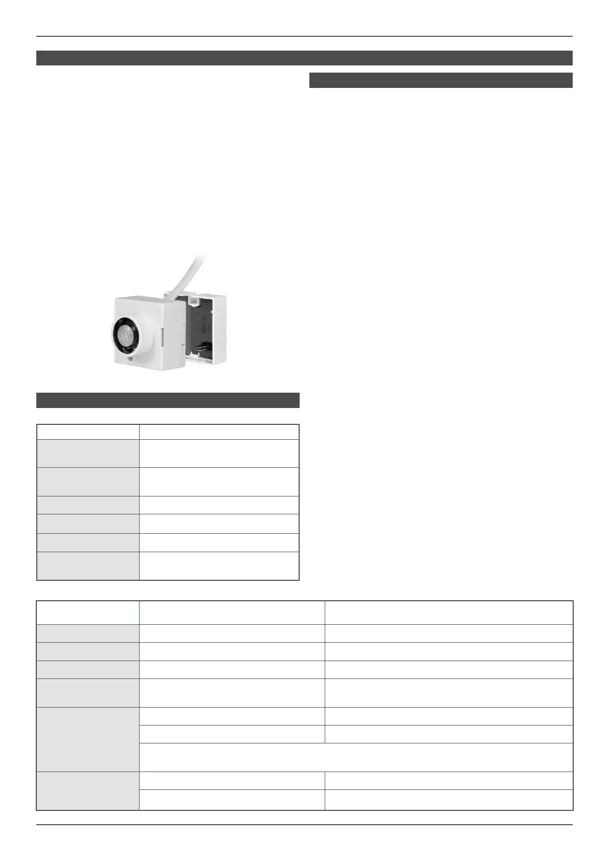
The SmartScan plug on module is factory installed on
the back of the Smart, Smart High-bay and Smart External sensors.
DEFAULT SETTINGS - Each SmartScan luminaire is delivered without
any addresses set and radio (RF) communications disabled. It is
important to set addresses correctly.
LED STATUS - SmartScan luminaires provide status feedback through
various coloured LEDs on each unit. The factory default is for radio status
Indication to be disabled to avoid user nuisance. This can be enabled
using the programmer.
EVENT DEFAULT BEHAVIOUR IF ENABLED BY SMARTSCAN PROGRAMMER
RF transmitted LED OFF Blue LED - ashes once
RF received LED OFF LEDs OFF
RF inhibit LED OFF Yellow LED - ashes once every 8 seconds
Join/leave/ping net-
work request
Blue LED - ashes for a maximum
of 60 seconds
Blue LED - ashes for a maximum
of 60 seconds
Join/leave/ping
network
successful response
Smart: Green LED - ashes 10 times Smart: Green LED - ashes 10 times
Emergency: Amber LED - ashes 10 times Emergency: Amber LED - ashes 10 times
NOTE: If no response is received after 60 seconds, the LED stops ashing, and reverts
to normal display (as dened above based on device address).
Join/leave/ping
network
unsuccessful response
Smart: Red LED - ashes 10 times Smart: Red LED - ashes 10 times
Emergency: LEDs OFF Emergency: LEDs OFF
EVENT DEFAULT BEHAVIOUR
Bright-out
Green LED - fast ash (1 second ON,
1 second OFF)
Permanent OFF
Green LED - slow ash (1 second ON,
4 seconds OFF)
Movement detection Red LED - ashes once
IR Programmer receive Red LED - ashes 3 times
100 hour burn in Red LED - permanent ON
Motionline short circuit
Red LED - fast ash (1 second ON,
1 second OFF)
 Loading...