36
SETTINGS
37
Adjust the Lower BRG Sub-Assembly up-
and-down, Pinion Gear Subassembly side-
to-side and Engine Mount side-to-side until
the gears mesh smoothly and t urn freely
with a minimum of backlash.
Always make sure the surface of the flybar,
flybar paddles, swashplate, and top of metal
frame are parallel.
38
On the left side frame, there are three pitch
scales molded onto the Pitch Guide. The
three differ ent scales are designed for
beginner, F3C and 3D pilots.
Use the "Pointer" on the collective tray and
the plastic molded scales to set up the initial
collective control.
The actual blade angle in degrees can be
checked using a pitch gauge (sold
separately).
13˚
12˚
0˚
-8˚
-9˚
0˚
13˚
12˚
-8˚
-9˚
POINTER
0˚
12˚
The hovering pitch angle should be at 5.5˚-6˚. To get the
0˚ to 12˚ collective range, mount the steel linkage ball at
10.5mm away from the center of the collective servo horn.
Adjust the servo rotation at 40˚ for both up and down. This
should give you the 0˚ to 12˚.
39
For F3C performance, there will be a different setting. The steel
linkage ball is at about 13-14mm away from the center of collective
servo horn. Adjust the servo rotation at 60˚ so the collective
travel range will be between -8˚ and 13˚. The servo horn will
be about 14˚ off the center when pointer is level with the 0˚ mark.
-8˚
0˚
13˚
For 3D hot-dog flights, the steel linkage ball is also at
about 13-14mm away from the center of collective servo
horn. Adjust the servo rotates at 60˚ so the collective
travel range will be between -10˚ and 13˚. The servo
horn will be about 9˚ off the center when pointer is level
with the 0˚ mark.
-10˚
0˚
13˚
40˚
40˚
10.5
14˚
60˚
60˚
13-14
9˚
60˚
60˚
Flying Adjustments (1)
44
43
Tracking adjustment ... When the two main rotor blades are in track it means their blade tips
should follow the same path as they rotate.
(1) Rev up the motor until the helicopter becomes
light on its skids.
(2) When the two main rotor blades are in
track it means their blade tips should follow
the same path as they rotate, then it's ok.
(3)
When two blades are in track, the blade tips will
appear overlapped as one look at the rotor tip
path plane from the edge.
If the blades are out of track, then adjust
one of the pushrods that connects to the
main rotor blade pitch arm.
Redo steps (1) to (3) until
the blades are tracking
properly.
In hover, the main blades should be
around 5.5 to 6 degrees in pitch.
out of track
in track
increase
throttle gently
and not too
much
45 46
Flying Adjustments (2)
Trimming: All helicopters are inherently unstable. But when a helicopter is properly trimmed, it
will not drift away or yaw by itself quickly. Use the following procedure to trim your
helicopter.
(1) If the helicopter nose starts to yaw left or right,
then
use the transmitter trim to compensate:
(3) If the helicopter noses down or up, then:
yaw right
yaw left
(A) situation: move to (b)
(B) situation: move to (a)
(2) If the helicopter rolls to left or right, then:
rolls right
rolls left
(C) situation: move to (d)
(d) situation: move to (c)
Noses down
Noses up
(E) situation: move to (f)
(F) situation: move to (e)
47 48
(4) It will take a few hours of hover practice with the helicopter skids at 10 to 20 cm (4-8 inches)
off the ground in order to comfortably control the model.
Do not try to lift the model to more than 10 to 20 cm(4-8 inches) in the beginning because
then the model may tip over readily when the beginner panics and an incorrect command is
given. Once you can keep the model at one place, then it is time to slowly increase the height
a few centimeters (inches) in each flight. Soon, you will be able to hover the helicopter
confidently at few feet high. Beginners should always practice hovering close to the ground
because in an emergency panic, throttle and collective can be reduced rapidly without causing
a large drop or damage to the model. If the model was hovering at beyond one meter(3 feet)
altitude, then always descend slowly. A panic drop can damage the helicopter.
(5) Always stand behind the model helicopter when learning how to hover because then you
can watch the nose of the helicopter, and a left tail rotor command will yaw the helicopter
nose to the left, and a right command will yaw to the right. Similarly, a left cyclic command
will cause the helicopter to translate left. After you can comfortably hover the model at one
meter high without drifting, then start practice hovering while standing to either side of the
model. Eventually, you need to be comfortable
at hovering the model from any orientation,
including with the helicopter nose pointing at
you, this is challenging because all control
directions are seem backward.
(6) Once you can confidently hover a model helicopter at any altitude and at any orientation,
then congratulate yourself because you have mastered 80% of the fundamental control
movements of a helicopter.
49 50
In the event the model has crashed.
Inspect the flybar, rotor shaft and the blade spindle to make sure they are not bent at all. If any item is damaged, it
must be replaced by a new part to ensure safe operation. Do not glue any broken or damaged plastic part. Do not
repair broken rotor blades. Always inspect the following items immediately:
(a).
Engine starting shaft.
(b).
All the gears.
(c).
Main shaft, flybar and blade feathering spindle.
(d).
Tail boom and supports for cracks.
(e). Drive shaft for the tail rotor.
(f).
Vertical and horizontal fins.
(g). Tail rotor shaft and control system.
(h).
Main and tail rotor blades.
(i).
Main frame.
A // B // C
The optional Pitch Gauge (#3802)
is recommended as shown.
Note:Recommended rotorspeed at 1500 rpm for hover and 1750 rpm for idle-up aerobatics.
TT has a full line of Optional Carbon Graphite rotor blades, please contact your local dealer for ordering these
high performance blades.
42
Always operate or fly a model helicopter in a safe manner and away from crowd, or spectators,
or distractions.
Do not operate model helicopters in rainy or windy condition.
Check to make sure there is no radio interference before operating a model helicopter.
Make sure the transmitter and receiver batteries are fully charged before operation.
Make sure all controls operate properly before flight.
Model helicopter main and tail rotors operate at high rpm, therefore make sure nothing can come
into contact with the rotors during flight.
Use only model engine fuel. Do not use gasoline, kerosene, or any other substitute.
Model engine fuel is highly flammable.
Do not let model engine fuel get in contact with eyes. Do not intake model engine fuel.
Range check the radio before flying. The servos must operate properly with the transmitter
antenna collapsed and at 20 meters away.
The engine must be in the idle position before starting the engine.
Make sure the transmitter and receiver are turned on before starting the engine.
Always maintain a safe distance when operating a model helicopter.
Do not fly a model helicopter above people or cars.
Flying requires concentration. Operating a model helicopter for extended time can cause fatigue.
Please rest in between flights.
Do not touch the engine or muffler immediately after the engine was run, because they will be
extremely hot.
Warning (Items to watch out after flight)
Inspect the model helicopter thoroughly to make sure nothing is loosen or damaged.
Pump out the remaining fuel from the fuel tank.
Lubricate every moving part with oil to ensure a smooth operation in the future.
Warning (For Storage)
Keep the model in a cool, dry place. Avoid storage under direct sun light or near heat.
Add some engine after-run oil through the carburetor, then crank the engine by an electric starter.
This help to prevent the engine bearings from rusting. After-run oils are available from hobby
shops.
Please replace any damaged parts if they are discovered during maintenance.
Attention
40
Advance 3-D SetupBeginner Setup
Use these number as a start only.
Program the radio values into the transmitter. The
EXPO should be to reduce the control sensitivity
near center stick, some radio manufacturer use
negative value and some use positive value. Adjust
the pushrods to the above lengths.Then fine tune
the lengths to get the desired blade angles. Fly the
model to fine tune the value.
Extreme 3-D Setup
Beginner Setup
Besides the original settings, we have provided an additional
setting for your reference. ( Suitable for extreme 3D flying)
The only difference being the Pushrod and servo horn setting
indicated with the instructions and the setting table below.
Elevator Rod Length: 66.5 69mm
Rudder Arm: 13.5 17mm
Pitch Rod Length: 77.5 73.5m
Pitch Arm: 18mm 19mm
Aileron Rod to swash: 66.5 68mm
Aileron Arm: 10.5 14mm
Swash to Hiller Assembly: 113.5 115mm
Additional Setting
[1]The engine will not start.
* The engine starting shaft will not turn:
The engine may be flooded with too much fuel. Please remove the glow plug first, then turn the engine
with the electric starter until the excess fuel spits out of the glow plug hole.
* The engine turns when the electric starter is applied, but the engine will not start:
(1) Is the glow plug working? Remove the glow plug and does the platinum coil glow red when a 1.5
volt battery is applied to the plug? The glow plug battery may be weak and old.
(2) Is the carburetor needle properly set? Please refer to the engine instruction manual for the proper
needle setting.
(3) Does the throttle control arm move properly and in the correct direction according to your transmitter
command?
* Engine will start, but quits immediately.
(1) Use the transmitter to increase the throttle carburetor slightly.
(2) Try a new or different type of glow plug. There are different types of glow plugs on the market for
different types of fuel and operating conditions. Seek the advice of experienced fliers and also
experiment with different types of glow plugs until you find the one that suits your operating condition
the best.
*Engine runs, but the helicopter will not lift off.
(1) Check the main rotor blade pitch angle, they should be set at 5.5 to 6 degrees when the transmitter
throttle/collective stick is at the center position.
(2) Does the engine throttle arm move properly? The carburetor opening should be fully open when
the transmitter throttle/collective stick is moved up. The carburetor opening should be nearly closed
when the transmitter throttle/collective stick is moved down. And the opening should be completely
closed when the transmitter throttle/collective stick is moved down and the throttle trim is also moved
down.
(3) The carburetor needle is not set properly. Close the needle (turn it clockwise) all the way, then
open the needle (turn it counter clockwise) 1 and 1/2 turns and try again. If the model still will not
lift, then the engine maybe running too rich. The symptom is the engine exhaust has a lot of smoke
and the engine coughs and wants to quit when the transmitter throttle/collective stick is moved up,
then close the needle 1/8 turn at a time, until the model will lift off. Do not turn the needle too far
inward, that will make the engine run too lean and over-heat and damage the engine.
[2] Helicopter problems.
* The helicopter shakes.
(1) Is the blade spindle bent?
(2) Is the flybar bent?
(3) Is the main rotor shaft bent?
(4) Are the two control paddles mounted at the same distance from the rotor shaft, and the paddles
are parallel to each other, and in the proper direction?
(5) Is the tail rotor shaft bent? The tail rotor blades mounted properly or damaged?
(6) Are the main rotor blades damaged or mounted in the proper orientation? The blade may require
additional balancing. The blade balance can be checked by removing both blades and then use
one of the 5mm blade bolt and nut to hold the two blades together like a teeter totter. Then, hold
the blade bolt with your thumb and index finger. The two blades should teeter and remain in a
level position. If not, then add some tape to the lighter blade near the blade tip until the two blades
teeter in a level position. Hobby shops also sell blade balancers that are designed solely for balancing
model helicopter blades.
The model helicopter should be thoroughly inspected after each flying session.
(1) Check every screw and bolt to make sure none has loosened due to vibration.
(2) Check every rotating and movable part to ensure they still move smoothly and normally.
(3) Clean off the exhaust residue from the muffler, engine, and helicopter.
(4) Check all movable parts, such as gears, ball links, belt, etc. for unusual wear.
41
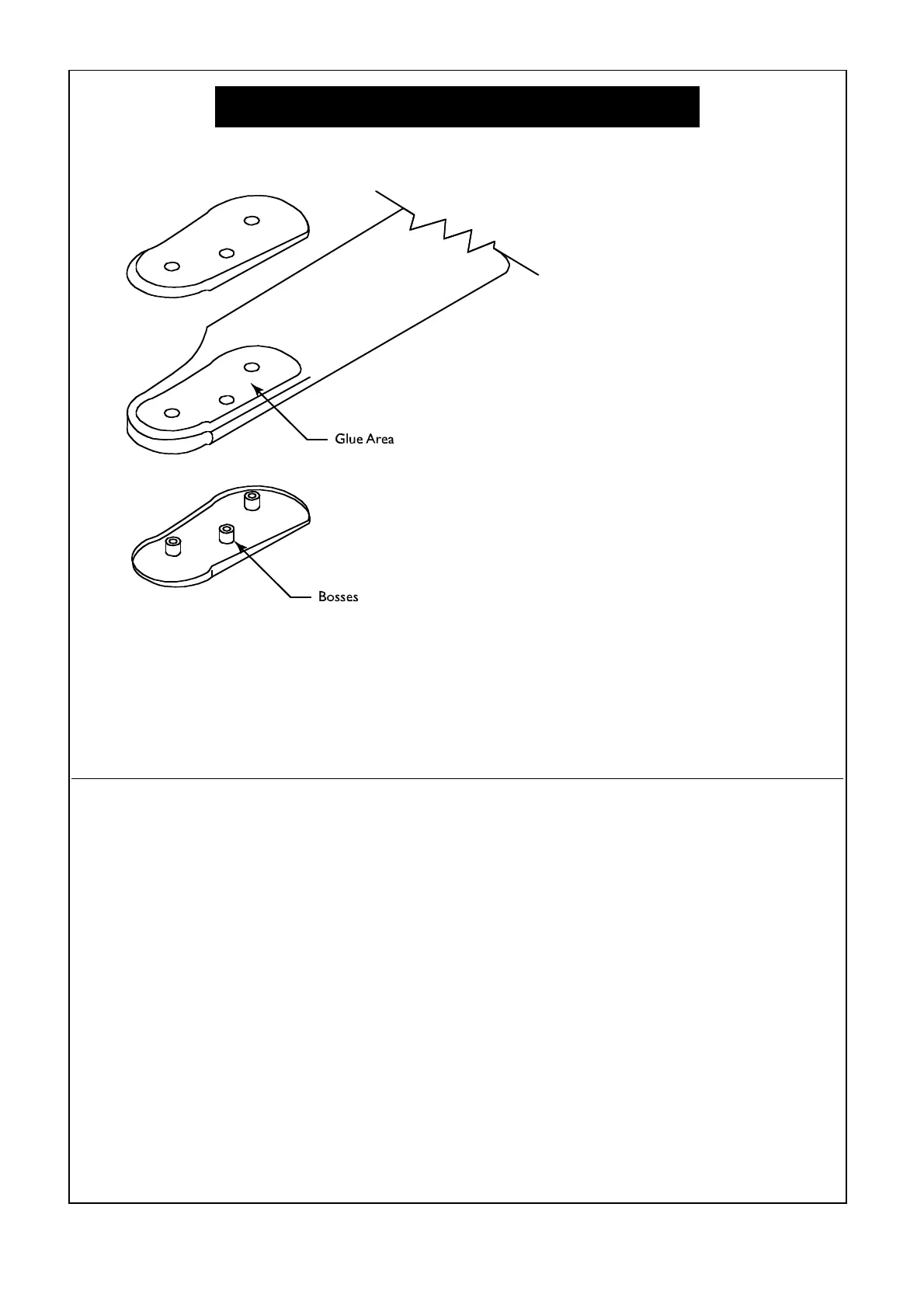
1. Mark around blade grips with a felt-tip marker.
2. Remove blade grips and cut covering lightly .125”
inside of mark, being careful not to cut into the blade.
3. Repeat for opposite side.
4. Trim bosses if necessary to allow tight fit to the blades.
5. Lightly sand inside of grips for better adhesion.
Apply Epoxy to blades in area shown top and bottom.
6. Attach blade grips and tighten screws.
7. Wipe off the excess Epoxy.
Idea and original art submitted by Randy Wishon,
Progressive Technologies, inc.
Dear Raptor Customers:
The stock wood blades should be operated with a main rotorspeed of no more than 1700 RPM. For 3D aerobatics
or rotor speed more than 1700RPM, it is recommended to use carbon main rotor blades. The above drawing
illustrate how to rem ove the plastic blade grips and then carefully slice away some of the covering material, and
add the "thin" type CA glue to further strengthen the wood. After installing the plastic blade grips, apply epoxy
around the seem of the plastic grip and the wood to seal it off. This adds more strength and prevent oil from seeping
through. For beginners, the best rotorspeed is around 1500 RPM. For advanced fliers, a good hovering RPM is
around 1500, and a constant 1800RPM in idle-up for 3D aerobatics.
Blade Modification
43mm
113.5mm
66.5mm
79mm
77.5mm
66.5mm
112mm
5˚ BEND
10.5mm
10.5mm
13.5mm
Pushrod length given
is fr om cente r to
cen ter of the bal l
links

 Loading...