No. Material No. Description Qty.
1 HMJ2-8N M2x8 Self-Tapping Screw 1
2 HSE2-10B M2x10 Self-Tapping Screw 2
3 HMC2510B M2.5x10 Socket Screw 4
4 HMM25 M2.5 Locknut 4
5 HMM3B M3 Locknut 2
6 HME3-18.5B M3x18.5 Set Screw 2
7
HMV1050ZZO
d5xD10x4 Angular BRG 4
8 HMV1060 d6xD10X3 BRG 2
9 BK0302-1 Tail Pitch Housing A 2
10 BK0303-1 Tail Pitch Housing B 2
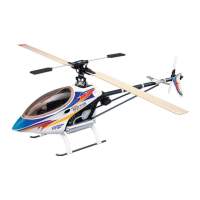
3-1-2 Tail Rotor Subassembly
1
3 5
MAIN FRAME ASSEMBLY
6 8 9 10 11 12 13 14 15 16 17
18
21
22
23
25 26 27 28
31
29
30 32
33
34
35
2
1-2-2 Tail Drive Unit Subassembly
1-3-1 Rod Guide Collar Subassembly
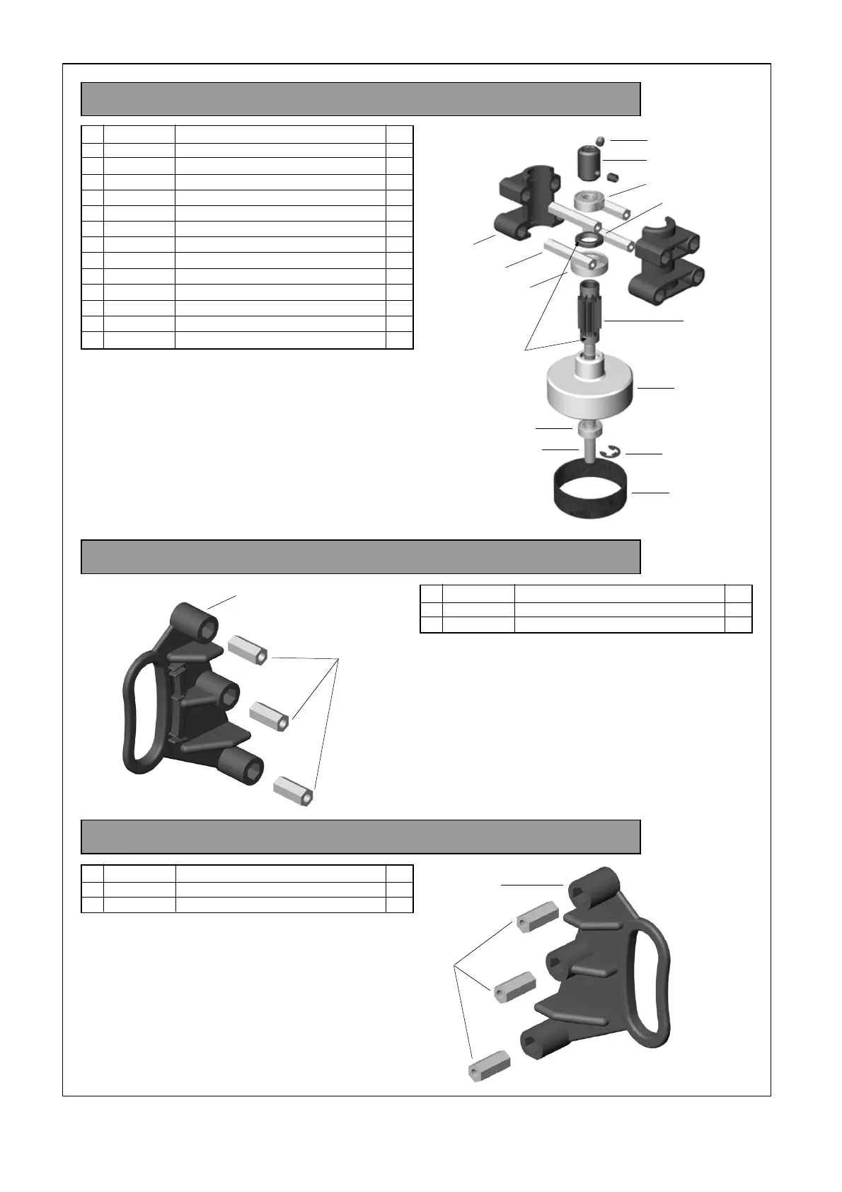
1-5-1 Aileron Lever Subassembly
1-5-2 Elevator Parallel Lever Subassembly
1-5-3 Elevator Control Lever Subassembly
1-5-4 Pitch Control Frame Subassembly
1-5-5 Elevator Control Arm Subassembly
1-6-1 Wash Out Subassembly
ROTOR HEAD ASSEMBLY
TAIL ASSEMBLY
3-1-1 Tail Transmission Subassembly
FINAL ASSEMBLY
4-2-1 Skid Subassembly
4-3-1 Tail Support Subassembly
INSTALLATION OF PERIPHERAL EQUIPMENT
5-5-1 Body Subassembly
No. Material No. Description Qty
1 BK0390 Frame Spacer L 2
2 HMC3-8B M3x8 Socket Screw 18
3 HMC3-10B M3x10 Socket Screw 4
4 HMC3-12B M3x12 Socket Screw 4
5 BK0087 d3xD8x1.4 Washer 4
6 BK0435 d4xD11x1.7 Washer 4
7 HMC4-12B M4x12 Socket Screw 4
8 BK0274 Tank Rubber Grommets 4
9 BK0349 Engine Mount 1
No. Material No. Description Qty
1 HMC3-25B M3x25 Socket Screw 10
2 BK0087 d3xD8x1.4 Washer 4
3 BK0103 Body Fitting Pin 2
4 BK0392 Frame Spacer S 2
5 1-3-1 Rod Guide Collar Subassembly 2
6 1-1 Upper Frame Assembly 1
7 1-2 Lower Frame Assembly 1
No. Material No. Description Qty
1 BK0389 Rod Guide Collar 1
2 BK0392 Frame Spacer S 2
No. Material No. Description Qty
1 BK0377 Servo Frame 1
2 HSE3-12B M3x12 Self-Tapping Screw 6
3 1-3 Main Frame Assembly 1
No. Material No. Description Qty
1 BK0093 2x46 Link Rod 1
2 HMC3-10B M3x10 Socket Screw 1
3 HMJ3-20N M3x20 Self-Tapping Screw 4
4 HMC3-25B M3x25 Socket Screw 1
5 BK0088 d3xD5x0.5 Washer 1
6 BK0020 Elevator Arm Shaft 1
7 1-5-1 Aileron Lever L Subassembly 1
8 1-5-1 Aileron Lever R Subassembly 1
No. Material No. Description Qty
1 HMJ2-10N M2x10 Self-Tapping Screw 2
2 HMV840ZZ d4xD8x3 BRG 2
3 BK0340 Aileron Control Arm 1
4 BK0075 Link Ball 4.8 2
No. Material No. Description Qty
1 HMJ2-10N M2x10 Self-Tapping Screw 2
2 HMV840ZZ d4xD8x3 BRG 2
3 BK0340 Aileron Control Arm 1
4 BK0075 Link Ball 4.8 2
No. Material No. Description Qty
1 HMJ2-8N M2x8 Self-Tapping Screw 1
2 BK0337 Elevator Arm Parallel Lever 1
3 BK0075 Link Ball 4.8 1
No. Material No. Description Qty
1 HMJ2-14N M2x14 Self-Tapping Screw 1
2 HMV840ZZ d4xD8x3 BRG 2
3 BK0338 Elevator Control Lever 1
4 BK0075 Link Ball 4.8 2
No. Material No. Description Qty
1 HMJ2-10N M2x10 Self-Tapping Screw 1
2 HMV840ZZ d4xD8x3 BRG 2
3 HMV1280 d8xD12x3.5 BRG 2
4 BK0336 Pitch Frame 1
5 BK0075 Link Ball 4.8 1
No. Material No. Description Qty
1 BK0339 Elevator Control Arm 1
2 BK0663 Elevator Arm Link 2
3 BK0413 Pin 2x29 2
No. Material No. Description Qty
1 BK0093 2x46 Link Rod 2
2 HMC3-6B M3x6 Socket Screw 2
3 HMM4B M4 Locknut 1
4 BK0617 M4 Bolt 1
5 BK0360 Main Shaft 1
No. Material No. Description Qty
1 HMJ2-10N M2x10 Self-Tapping Screw 2
2 HMC3-12B M3x12 Socket Screw 2
3 HMV840ZZ d4xD8x3 BRG 4
4 BK0341 Wash Out Base 1
5 BK0342 Flybar Control Lever 2
6 BK0343 Wash Out Link 2
7 BK0075 Link Ball 4.8 2
8 BK0409 Collar d3xD4x7 2
9 BK0412 Pin 2x14.5 2
No. Material No. Description Qty
1 HMM3B M3 Locknut 4
2 HSE3-12B M3x12 Self-Tapping Screw 2
3 HMC3-14B M3x14 Socket Screw 2
4 HMC3-30B M3x30 Socket Screw 2
5 BK0348 Tail Control Rod B (In BAG O) 1
6 BK0430 Tail Boom (In BAG O) 1
7 BK0403 Rod Guide 3
8 BK0399 Vertical Fin 1
9 BK0400 Stabilizer Fin 1
No. Material No. Description Qty
10 BK0401 Stabilizer Fin Bracket 1
11 BK0404 Tail Rotor Blade 2
12 BV0423 Tail Drive Shaft BRG (In BAG O) 1
13 BV0367 Tail Drive Shaft (In BAG O) 1
14 3-1-1 Tail Transmission Subassembly 1
15 BK0086 Ball Link 4.8x20 1
16 HMC2612B M2.6x12 Socket Screw 2
17 HMM26B M2.6 Locknut 2
No. Material No. Description Qty
1 BK0318 2.3x95 Link Rod 2
2 HMM4B M4 Locknut 1
3 BK0617 M4 Bolt 1
4 2-1 Rotor Head Assembly 1
5 BK0086 Ball Link 4.8x20 4
No. Material No. Description Qty
1 HMJ4-22N M4x22 Self-Tapping Screw 4
2 4-2-1 Skid Subassembly 1
o. Material No. Description Qty
1 HME4-5B M4x5 Set Screw 4
2 BK0397 Skid Brace 2
3 BK0276 Skid Pipe 2
4 BK0398 Skid Pipe End Cap 4
No. Material No. Description Qty
5 BK0087 d3xD8x1.4 Washer 2
6 3-1 Tail Assembly 1
7 4-3-1 Tail Support Subassembly 2
No. Material No. Description Qty
1 HML2 M2 Nut 4
2 HMF2-8N M2x8 Philip Machine Screw 4
3 BK0436 2.3x55 Link Rod 2
4 BK0438 2.3x88 Link Rod 1
5 HSE2614N 2.6x14 Self Tapping Screw 12
6 HME4-5B M4x5 Set Screw 2
No. Material No. Description Qty
1 HML2 M2 Nut 3
2 HMF2-8N M2x8 Philip Machine Screw 3
3 BK0436 2.3x55 Link Rod 1
4 BK0095 2.3x76 Link Rod 1
5 HSE2614N 2.6x14 Self-Tapping Screw 8
No. Material No. Description Qty
1 ***** Switch JR Type 1
2 ***** Swtich Plate 1
3 ***** Battery(Recommend 1200mA) 1
4 ***** Reciever 1
No. Material No. Description Qty
1 5-5-1 Body Subassembly 1
No. Material No. Description Qty
1 HMJ2-6B M2x6 Self-Tapping Screw 6
2 HSE3-12B M3x12 Self-Tapping Screw 2
3 BK0102 d3xD6x11Grommet 2
4 BK0098 Body Clip A 1
5 BK0099 Body Clip B 1
6 BK0429 Body 1
7 BK0428 Canopy 1
8 JV0010 Decal 1
9 BK0473 Body Support 1
10 BK0474 Rubber CAP 2
11 HNLR6 R Pin 2
No.Material No.DescriptionQty
1BV0383Main Rotor2
2BK0446M5x35 Rotor Bolt2
3HMM5ZM5 Locknut2
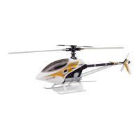
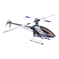
Thank you very much for purchasing the Thunder Tiger/Taya "Raptor 60" helicopter. Mr. Taya, the first F3C
Helicopter World Champion, designed this helicopter to be the highest quality model helicopter in the RC
hobby industry. The Raptor 60 is designed for modelers who love building and flying model helicopters.
Only the highest quality materials are used. With the Raptor, the pilot can really appreciate the pleasure of
flying in 3-dimensional space. Its docile handling is ideally suited for beginners. The stable hover and agility
also make it the top choice for contest fliers and extreme 3-D pilots. The Raptor requires the least amount
of assembly of any helicopter kit. The ARF version comes complete with a high performance Thunder Tiger
Pro 70H ring engine and muffler. The helicopter and engine are both manufactured by Thunder Tiger using
the most modern technology and exceed the stringent internationally recognized ISO-9001 manufacturing
standard. We have incorporated all the state-of-the-art technology into designing and making this helicopter.
We believe you will enjoy this model for a long time. We have made no compromise in designing or
manufacturing this model.
Unique Sideframe System
Aluminum side plates are used in conjunction with molded material to construct the main structure. This
design produces a minimum weight with maximum strength. If the sideframes were completely made of
molded material, then to achieve equal strength the plastic would have to be very thick and heavy. Using
molded material at the right place avoids using metal angle brackets or putting compound bends in metal
frames. Slots have been added in the frame design to permit using optional gear ratios to optimize engine
performance to suit any pilot's demand.
Bell-Hiller Mixing Control Unit
Main rotor control geometry has been carefully engineered to minimize cross-coupling in collective and cyclic
commands. Blade pitch arms and the Bell-Hiller mixing arms are designed at an angle such that the pushrod
interlinking them are at 90 degrees when the blades are at 0 degree. The pilots will get the symmetrical
cyclic control feel and flybar authority either at +10 or -10 degrees of collective. We designed this system
with the 3-D pilot in mind. We guarantee you this whole design philosophy provides a strong and accurate
control mechanism.
Shaft Drive Tail Rotor
The Raptor 60 is designed with a constant drive tail rotor system to permit full tail rotor control during
autorotations. Backward autos, pirouette autos and 180 autos are all within your reach now. It has the same
aluminum torque tube system as the Thunder Tiger/Taya Imperio helicopter. This allows obtaining the
maximum performance from any modern high gain gyros.
3D CAD Design
We used modern 3D Computer Aided Design to design and manufacture the Raptor 60. Our high-tech CAD
program allows simulation of all the moving part to ensure non-interference. The analysis automatically
analyze the weight, the mass distribution, and inertia to help us pursue a design that will provide the high
level of maneuverability needed for all-out 3-D aerobatics.
Instruction
Repair and replacement Parts
Purchase replacement parts from the hobby shop where you have purchased the Raptor 60. Please contact the Thunder
Tiger distributor in your country, and the distributor can tell you where to obtain the parts. For example, in the U.S, all
Thunder Tiger products are distributed by Ace Hobby Distributors. On the web site www.acehobby.com, there is a list
of all the hobby shops in the USA that can special order any Thunder Tiger parts from Ace for you. Technical questions
on the Raptor will be answered quickly sending an email to service@acehobby.com or call Technical Support at 949-
833-7498. In Europe, Asia and Australia, please contact the distributor in your country.
Warnings
To ensure safety, please read the instruction manual thoroughly before assembly. Radio control helicopters are
sophisticated equipment, and not toys. Radio control model helicopters are capable of causing serious bodily injury if
not properly assembled or operated. The manufacturer and distributors assume no liability for damages that could
occur from the assembly or use of this product. This product is designed for hobby use only. Operating model Helicopters
requires diligence and skill. It is best to seek help and guidance from other accomplished model helicopter pilots to
ensure quick and successful learning. It is strongly recommended to join the appropriate radio control modeling governing
society in your country. For example, in the United States, it is strongly encouraged to join the Academy of Model
Aeronautics. AMA is a nonprofit organization that provides members in the United States with liability insurance and
monthly modeling magazines. For further information or to find a model
helicopter club that's nearest to you, please contact AMA at:
Academy of Model aeronautics
515 East Memorial Drive
Muncie, IN 47302
USA
(317) 287-1256
We also encourage start subscribing to different radio control helicopter magazines to learn about RC flying events,
new flying techniques, safety procedures, and hints. Rotory Modeler is a bi-monthly and Model Helicopter Techniques
is a quarterly newsletter published in the USA. Model Helicopter World is a month magazine published by Traplet
Publication in England and sold worldwide. Rotor is a monthly German magazine. Helico is a Swiss quarterly magazine.
Attention
We are unable to accept replacement or return of this model after it has been used or assembly has begun.
It is legally prohibited to duplicate or reprint this manual in any format without a written permission from the manufacturer.
The manufacturer has the right to make changes to this model or instruction without notice.
We have done our best to ensure the accuracy of information in this manual. If you are aware of any mistake, we
welcome you to notify us.
We will not accept any responsibility for any accident, breakdown, fault or trouble caused by improper usage of this
model. Please thoroughly inspect your model and range check the radio before flight. Please keep the model in its
best condition in order to enjoy it.
This model does not include all the items necessary for flying. It still needs a helicopter radio control system, a 60-
size 2-stroke engine, and a muffler.
It is difficult for beginners to fly RC helicopters by themselves. It is highly recommended that beginners seek the help
of experienced RC helicopter pilots. We recommend beginners start with an inexpensive model such as the Thunder
Tiger Raptor 30 that is also designed by Mr. Taya.
RC helicopters are not toys. The manufacturer does not assume the liability for any property or bodily damage caused
by the model or the operator.
OTHER ITEMS REQUIRED
4
The two plastic elevator control arms should be attached to the swashplate
steel ball with the molded character number facing the swashplate ball. Because
the hole on the plastic control arm has difference opening sizes on the two
sides. The side with the molded character number has the bigger opening.
Please snap this plastic control arm gently onto the swashplate steel ball and
afterward, please check to make sure it is securely attached and there is no
damage or cracking.
The looped shape plastic control rod should be attached to the flybar control
arm with the molded character facing the steel ball. Please check to make
sure it is securely attached and there is no damage or cracking.
INSTALLATION OF THE RODS
Character No.
Character No.
MARK
MARK
BODY SUPPORT INSTALLATION
Insert the aluminum support
tube through the servo frame.
It may be necessary to drill
out the hole in the servo frame
to 1/4" (6.1mm)
Insert the "R" pins through the
two holes in the support tube
so it will be retained in the
servo frame.
Install the two rubber ends onto
the support tube. The rubber
ends will dampen shake or
vibration generated by the
body.
Glow Plug Wrench
12V Battery
1.5V Glow starter
(1.2V~1.5V)
Rubber Band
(Included)
Foam
Remote Glow Plug
Extension
Training Gear
(for beginners only)
1-2-3 Cooling Fan Casing Subassembly
No. Material No. Description Qty
1 BK0378 Fan Casing L 1
2 BK0379 Fan Casing R 1
3 BK0390 Frame Spacer L 4
Optional: add a tiny drop of thick CA on the outside rim
of the ball bearings before inserting them into the plastic
Pitch Frame. Be careful not to get any glue into the ball
bearings. Add a tiny drop of thick CA glue at the tip of
the M2x10 self-tapping screw (No. 1) before
screwing it into the Pitch Frame.
19
20
No.Material No.DescriptionQty.
1BK02922.3x24 Link Rod2
2HMC3-10BM3x10 Socket Screw2
3HMV694ZZd4xD11x4 BRG2
4BK0408Collar d3xD4x5.52
No.Material No.DescriptionQty.
5BK0086Ball Link 4.8x204
62-1-1Flybar Seesaw Subassembly1
72-1-2Main Rotor Hub Subassembly1
2-1-1 Flybar Seesaw Subassembly
2-1-2 Main Rotor Hub Subassembly
24
No. Material No. Description Qty.
1 HMV6701Z d12xD18xBRG 2
2 HMJ2-8N M2x8 Self-Tapping Screw 1
3 HMM3B M3 Locknut 3
4 HME3-4B M3x4 Set Screw 1
5 HMC3-10B M3x10 Socket Screw 3
6 HMY2-12 Pin 2x12 1
7 HMJ3-20N M3x20 Self-Tapping Screw 1
8 BK0088 d3xD5x0.5 Washer 1
9 HMV740ZZ d4xD7x2.5 BRG 2
Since there are many after-market carbon fiber and fiberglass
blades on the market now with a 12 mm thick blade root, Thunder
Tiger has now added a complimentary Blade Grip Spacer with
each Raptor 60 Kit. This spacer is specially designed for carbon
fiber or fiberglass blades with a 12mm thick blade root. The
spacer SHOULD NOT be used on any brand or type of wood
rotor blades, including the stock Raptor 60 wood blades because
the space do not provide strength: it is just a spacer. To install
the spacer, simply bend it over and put it in place. If the blade
root is more than 12 mm, then do not use this spacer and use
the washer that comes with your blades.)
Thunder Tiger provides a good selection of high performance
680mm carbon fiber rotor blades (TTR 3836). Please check
your local dealer for more information on upgrading your rotor
blades.
See wood blade modification in page 41.
1-6-3 Main Gear Subassembly
No. Material No. Description Qty
1 BV0368 Auto Rotation Clutch 1
2 BK0420 Main Spur Gear 93 1
3 BK0357 Tail Drive Spur Gear 83 1
4 HMQ16 Retaining Ring 1
5 HMC3-8B M3x8 Socket Screw 4
6 BK0359 One Way Clutch Shaft 1
7 BK0613 One Way Clutch Reinforced Ring 1
8 HMC3-14B M3x14 Socket Screw 1
Reinforced Ring
No. Material No. Description Qty.
11 BK0307 Tail Rotor Hub 1
12 BK0025 Tail Pitch Control Fork 1
13 BK0026 Tail Pitch Control Link 2
14 BK0027 Tail Pitch Control Slider 1
15 BK0345 Tail Pitch Control Slide Bushing 1
16 BK0374 Tail Shaft 1
17 BK0075 Link Ball 4.8 1
18 BK0082 Collar d2xD3x4 2
19 BK0083 Pin 2x9 2
Assemble the Tail Pitch Control Slider and Pitch Control Fork
according to the drawing as follows. Insert bearings No. 8
Bearings into No. 14 Tail Pitch Control Slider. Add a tiny drop
of Loctite on the "outside" surface of No. 15 Tail Pitch Control
Bushing, then slide it into the two bearings in the No. 14 Tail
Pitch Control Slider. Thread the No. 12 Pitch Control Fork onto
the brass bushing until the bushing does not have any in and
out play, but the pitch fork should still be able to spin freely in
the bearings. Add a No. 17 Link Ball with a No. 1 Screw. Then
slide the finished pitch slider onto the tail shaft.
Now assemble the Tail Blade Grip System. First install the No.
11 Tail Rotor Hub onto the No. 16 Tail Rotor Shaft. The hub
will be almost flush with the end of the tail rotor shaft. Secure
the hub to the shaf t by using two No. 6 M3x18.5 set screws.
Add a tiny drop of Loctite on the set screw before threading
them into the hub . If too much Loct ite is used then it will be
impossible to remove the set screws for service in the future.
A tiny drop of Loctite is sufficient to prevent them from vibrating
out. Put a tiny drop of Loctite on t he inside surface of No. 7
Bearings. Then slide two No. 7 bearings onto each end of the
tail rotor hub. Add the No. 6 3mm locknut. Do not over tighten
the two locknuts because that may break the No. 6 set screw.
Now add the two piece plastic No. 9/10 Tail Pitch Housings.
Install No. 13 Tail Pitch Control Links, No. 18 Collars, and No.
2 Screws according to the drawing.
Attach the Tail Pitch Control Links No. 13 to the Pitch Fork using
the small pins, No. 19.
(1)
(3)
(4)
(6)
(5)
(2)
Please complete subassemblies 1-5-1 through 1-5-5 first, then add them to the Main Frame. Insert the completed Elevator Control
Arm Subassembly No. 12 in between the Upper Metal Sideframes first. Then fit the plastic Pitch Control Frame Subassembly.
Next insert Items No. 6 Elevator Arm Shaft and No. 9 Elevator Parallel Lever Subassembly. Then secure the plastic Pitch Control
Frame using No. 2 Socket Screw and No. 14 Collar on the left side and then No. 14 Collar, No. 5 Washer, No. 10
Elevator Control
Lever
Subassembly, No. 15 Collar and No. 4 Socket Screw for the right side. Adjust the two bolts (No. 2 and No. 4) so the
Pitch Control Frame can rock freely but without excessive play. Finally, add the two plastic Aileron Levers and the 66.5 mm
pushrod. (Refer to Page 45 for actual measurement.)
Before installing the Aileron Levers (No. 7 and No. 8), please add a small drop of Loctite on the M3x20 socket screw (No. 3) and
on the outside of the collar d3xD4x13 (No. 15). Please do the same for parts No. 2 and No. 14 and No. 4. And No. 15.
1-1 1-2
(13)
(1)
(16)
(2)
(8)
(11)
(17)
(7)
(6)
(10)
(1)
(9)
(15)
(12)
(9)
(3)
(2)
(1)
(5)
(8)
(11)
(6)
(7)
(10)
(4)
1-3
(1)
(3)
(2)
(5)
(4)
(2)
(1)
1-4
(1)
(2)
(2)
(1)
(4)
(3)
(1)
(4)
(2)
(3)
(2)
(3)
(1)
(1)
(4)
(2)
(3)
(1)
(5)
(4)
(2)
(3)
1-5 1-6
(3)
(9)
(4)
(6)
(2)
(1)
(10)
(8)
(7)
(5)
(1)
(7)
(3)
(8)
(2)
(9)
(6)
(5)
(4)
2-1
3-1
4-1
(4)
(2)
(1)
(5)
(3)
4-2
(2)
(1)
(4)
(2)
(1)
(3)
180mm
25mm
4-3
(2)
(6)
(1)
(4)
(1)
(5)
(3)
(7)
(1)
(2)
(3)
5-1
(3)
(1)
(2)
(4)
5-2
(6)
(8)
(9)
(3)
(11)
(1)
(2)
(10)
(5)
(12)
(7)
5-3
(3)
(1)
(2)
(9)
(5)
(8)
(4)
(7)
5-4
(6)
(2)
(8)
(1)
(5)
(4)
(3)
(7)
5-5
(1)
(6)
(3)
(7)
(5)
(1)
(4)
(2)
5-6
(1)
(2)
(3)
No. Material No. Description Qty
10 BK0376 Lower Metal Frame 2
11 BK0380 Rear Frame L 1
12 BK0381 Rear Frame R 1
13 1-2-2 Tail Drive Unit Subassembly 1
14 1-2-1 Lower BRG Subassembly 1
15 1-2-3 Cooling Fan Casing Subassembly 1
16 1-2-4 Fuel Tank Subassembly 1
17 BK0629 Washer 4
(3)
No. Material No. Description Qty
9 1-5-2 Elevator Parallel Lever Subassembly 1
10 1-5-3 Elevator Control Lever Subassembly 1
11 1-5-4 Pitch Control Frame Subassembly 1
12 1-5-5 Elevator Control Arm Subassembly 1
13 BK0086 Ball Link 4.8x20 2
14 BK0407 Collar d3xD4x4.5 2
15 BK0410 Collar d3xD4x13 3
No. Material No. Description Qty
6 BK0234 Lock Ring 1
7 1-6-1 Wash Out Subassembly 1
8 1-6-2 Swash Plate Subassembly 1
9 1-6-3 Main Gear Subassembly 1
10 BK0086 Ball Link 4.8x20 4
No. Material No. Description Qty
1 HMM3B M3 Locknut 6
2 HSE3-12B M3x12 Self-Tapping Screw 2
3 HMC3-20B M3x20 Socket Screw 2
4 HMC3-25B M3x25 Socket Screw 4
No. Material No. Description Qty
1 HMJ2-8N M2x8 Self-Tapping Screw 4
2 BK0447 Tail Support Rod End 4
3 BK0396 Tail Support Rod 2
No. Material No. Description Qty
1 5-1-1 Engine Subassembly 1
2 HMC4-18B M4x18 Socket Screw 4
3 BN1639 Muffler 1
No. Material No. Description Qty
1 ***** Heli Engine .60~.70 1
2 HMC4-8B M4x8 Socket Screw 2
3 ***** Nut ( Comes with Heli Engine) 1
4 HMO10 d9.5xD16x1 Washer 1
5 BV0380 Cooling Fan 1
6 BV0381 Clutch 1
No. Material No. Description Qty
7 ***** Servo 5
8 BK0105 Rod Joint 1
9 BK0347 Tail Control Rod A (In BAG O) 1
10 BK0075 Link Ball 4.8 4
11 BK0086 Ball Link 4.8x20 7
12 BK0104 Servo Mounting Plate 6
No. Material No. Description Qty
6 ***** Servo 2
7 BK0075 Link Ball 4.8 3
8 BK0086 Ball Link 4.8x20 4
9 BK0104 Servo Mounting Plate 4
No. Material No. Description Qty
5 ***** Gyro AMP 1
6 ***** Gyro 1
7 BK0106 Two Touch Tape 2
8 BE1052 Antenna Pipe 1
BAG A
BAG B
(14)
(3)
(4)
(4)
BAG C BAG D
BAG E
(L)
(R)
BAG F
BAG G
BAG H
BAG I
BAG J
BAG J
(6)
Refer 6-3
Collective Pitch Setting
97.5mm
77.5mm
(4)
Throttle
Collective Pitch
BAG J
BAG K
BAG L
BAG M
Please complete the subassembly steps 1-2-1 through 1-2-4 first. Then attach the subassemblies to the two Lower Metal Frames.
Note that the Lower BRG Subassembly is installed upside-down. Please add a small drop of Loctite on every bolt before screwing
it into the aluminum hex spacer.
Assemble the upper main frames by starting with the two Upper Metal Frames. The Upper BRG Subassembly and Clutch/Pinion
Gear Subassembly must be assembled first according Figure 1-1-1 and 1-1-2. Also insert three hex-shape frame spacers into
the plastic Pitch Guide according to Figure 1-1-3 and 1-1-4. Then attach the finished subassemblies to the Upper Metal Frames.
Note that the two button head bolts (No. 3) are inserted and remain loose until later when they are used to secure the Body
Fitting Pins in Step 1-3. Locate Hex Wrenches in BAG K which you will use in assembly.
Please add a tiny drop of non-permanent type Loctite on the tip of the bolts before screwing them into the hex shaped aluminum
frame spacers. Never use too much Loctite, otherwise it will become nearly impossible to remove the screw later on for servicing.
Only use the non-permanent type of Loctite. If encountering difficulty in removing any bolt that was locked up by Loctite, then
heat up the head of the scare or bolt with the tip of a hot soldering iron which will help soften the cured Loctite.
For the kit, parts are bagged according to each major assembly and are labeled "Bag A, Bag
B, etc." You will note that the heading for each assembly indicates which bag correlates with
each assembly. As a good practice, only open up the bag that you need for the particular
assembly. Check the parts in that bag against the parts list shown for each assembly as well
as each sub-assembly to make sure there are no missing parts. To prevent losing small
hardware, please empty the small nuts and bolts and parts into small plastic trays on your
work table. At the end of each major assembly, there should be no left over parts.
(6)
(7)
Install BK0364 and BK0362 onto BK0365 Tail Gear Drive
Shaft. Then insert the two Pins and secure them with two
M3x4 Set Screws. Add a tiny drop of Loctite on the set
screw thread before inserting them. Always use a very
small amount of Loctite liquid on the thread, otherwise it
may be nearly impossible to remove the set screws in the
future for servicing. Install the four ball bearings and the
hex shaped Frame Spacers according to the drawing.After
installing the two M3x4 set screws (No. 2), try push on the
2x12 pins with a small Allen wrench to make sure the set
screws have locked the pins in place securely. Before
closing the two halves of the Tail Boom Brackets, please
check the gear mesh between gears No. 4 and No. 5. If
there exists too much freeplay, then add some 5 mm i.d.
washers on top of gear No. 4. (The 5 mm i.d. washers
are not provided).
Install the silicone fuel line to the Fuel Nipple. Then add the rubber
fuel tank stopper and the clunk weight. The stock silicone fuel line
is very soft and thin and is designed to allow the clunk to pick up fuel
easily during 3-D aerobatics. The pickup line should be inspected
and replaced if necessary every month, otherwise when it becomes
soggy it can break off. A thicker silicone line maybe substituted but
make sure the clunk will reach the bottom when moving the fuel tank
to all different orientations.
(1)
(2)
(3)
Insert two hex Frame Spacers S into
the plastic Rod Guide Collars (1-3-1).
Then join the Upper Frame Assembly
to the Lower Frame Assembly according
to the drawing. Do not forget to install
the four taper washers (2) under the
bolts for the Rod Guide Collars. The
two Body Pins (BK0103) will be used
to secure the canopy in the future. Add
Loctite on all bolts and inside BK0103
threaded hole.
Install the one-piece servo frame using six self-tapping screws.
Do not use Loctite when attaching self-tapping screws to plastic
parts. Loctite is only for threading metal into metal parts.
(11)
(14)
(2)
(15)
(7)
(3)
(6)
(12)
(9)
(8)
(13)
(4)
(1)
(15)
(10)
(5)
(14)
(3)
Assemble the constant drive Main Gear Subassembly according to Figure 1-6-3 first. Then build-up the Wash Out Subassembly
and Swash Plate Subassembly according to 1-6-1 and 1-6-2. Insert the No. 5 Main Shaft into the bearings and then add the
No. 6 Lock Ring and the slide through the Main Gear Subassembly. Do not over tighten the M4x25 bolt, otherwise the BK0359
Shaft will be distorted and prevent the Autorotation Clutch from turning freely. Add the M3x6 Socket Screw to the Locking Ring.
Slide the Locking Ring all the way up until the rotor shaft has no up and down play, then tighten the M3x6 Socket Screw.
Insert the pin into the Washout Link. If the link is tight
on the mixing arm, then gently squeeze the Link at the
pin position with a pliers while the Link is attached to
the Arm. This will make the hole in the Link slightly
bigger. You may want to add just a tiny drop of Loctite
on the inside and outside of BK0409 Collar which will
help give a completely slop free control system. Do not
let the Loctite seep into the bearing. Adjust the tightness
of the M3x12 bolts so the mixing arms can move freely
but without wobble or racheting the ball bearings.
Assemble the Tail Transmission Subassembly according to 3-
1-1 first. But do not close the two halves of the transmission
tightly. You will do this when you are ready to install the gearbox
onto the tail boom.
When installing the Tail Transmission make sure the housings
match the hole on the tail boom. Tighten the five 3 mm bolts.
Add the No 8 Vertical Fin and lock nuts.
Insert the No. 13 Drive Shaft into the tail boom. Make sure the
No. 12 Tail Drive Shaft Bearing slides through the tail boom.
This Bearing should be cl ose to the cent er of the dr ive sha ft
but it is not important exactly where it is. Secure No.16 Socket
Screw and No.17 Locknut at two ends. Slide three No. 7 Rod
Guides onto the tail boom. Do not glue them onto the tail boom
yet. Add a tiny drop of CA glue to the pushrod guide after you
finish building the entire helicopter. Before adding glue, make
sure the tail pushrod is hooked up to the servo and the rod
travels in a straight line and moves very smoothly.
Add the No. 9 Stabilizer Fin and No. 10 Bracket now.
Add the No. 11 Tail Rotor Blades using No. 3 Bolts and No. 1
Locking Nuts.
Congratulation, we are almost done. Install the finished main
rotor head onto the 12 mm rotor main shaft. Secure it with a
No. 3 M4x25 socket bolt and No. 2 4 mm locknut. Make up two
113.5 mm long pushrods and attach them to the Bell-Hiller
mixing arm.
Before installing the plastic end caps, please
add a drop of slow, thick CA glue on the
rim of the end caps and on the inside edge
of the aluminum skid.
Slide the finished tail boom into the helicopter. The bolts on the
helicopter must be loose in order to insert the tail boom. Make
sure the tail drive shaft is inserted into the front receptacle
properly. Check this by turning the main rotor head. Secure
the tail boom by tightening the screws on the helicopter. Visually
check to make sure the tail rotor output shaft is perpendicular
to the main rotor shaft. Add the tail boom supports.
Secure the two plastic ends to the aluminum
tube with slow CA or epoxy glue and the
two 2 mm self tap screws, making sure the
two plastic ends are perpendicular to each
other.
No. Material No. Description Qty
4 HMC4-42B M4x42 Muffler Bolt 2
5 HMT4B SPRING WASHER 2
(5)
Insert the engine into the sideframes,
then add the muffler.
Add a drop of Loctite on the threads of
the M4x42 muffler bolts.
The aluminum cooling fan hub is threaded. Place the washer that came with
your engine onto the engine crankshaft first. Then screw the fan hub onto the
engine. Add a tiny drop of Loctite on the engine nut. Do not use to much
otherwise the nut will be impossible to remove later on. Tighten the engine nut
using a socket head wrench while grabbing the plastic fan with a towel. The
nut should be tighten securely, but do not over torque it because you may
damage the plastic fan, or the plastic fan may come apart from the aluminum
fan hub. For 50-size or bigger engines, we do not recommend using a piston
locking tool on the glow plug hole because that may damage the engine. Attach
the No. 6 Steel Clutch, to the fan hub.
Add a drop of
Loctite on the threads of the M4x8 bolts. The threads on the
aluminum cooling fan hub are for the TT70H or the OS 61 SX and OS 61 LX
engines. If YS 61 ST II engines are used, then the fan hub must b re-tapped
by the modeler or purchase optional fan hub with threads for the YS engine.
10.5
10.5
10.5
10.5
Aileron Servo Horn
JR Type Futaba Type
10.5
Elevator
JR Type Futaba Type
10.5
JR Type
Futaba Type
Rudder
13.5
13.5
Install the servos and make up the pushrods according to the drawings. The distance between the steel ball and the center of
servo arm are shown in the drawing. Use them as a guide. These distances are used in conjunction with the servo travels set
to 100% for all the channels in the transmitter. Fine tune them to suit your personal flying style.
Make up the throttle and collective control pushrods according
to the drawing. Use the outermost hole on the throttle control
arm. Attach the steel ball on the throttle servo arm at approximately
the same distance as the steel ball on the throttle arm.
Install the receiver and receiver battery. Even though the receiver and battery can be attached to the helicopter tray using double
sided foam tape, but it is better to wrap the receiver and battery separately using half inch or 1o mm thick foam. Then secure
them to the tray using six to eight rubberbands.
Carefully cut out the transparent canopy
(windshield) using a scissors. The best
scissors to use are the ones designed to cut
RC car bodies. Install the canopy to the body
using six small screws. Drill small holes in
the canopy and body for the holes. Drill two
more holes for the rubber grommets.
Refer to color box and apply
the decals
(In BAG O)
.
Tools for Assembly
The Raptor 60 design has a low parts count. It is designed for easy maintenance using standard hobby tools. Please only use
genuine Thunder Tiger parts. Please keep the model clean and well tuned. It will provide you with long lasting pleasure in return.
(6)
Notice there is a Fuel Plug (No.6) furnished
for your convenience. You wnat to install a
three way manifold to simplify the fueling
process.
Apply Grease
(Included)
Add a tiny drop of thick CA glue at the tip of the M2x10
self-tapping screw (No. 1) before screwing it into the
Aileron Levers.
Add a tiny drop of thick CA glue at the tip of the M2x18 self-tapping
screw (No. 1) before screwing it into the Flybar Control Levers
(No. 5). Before installing the Flybar Control Lever (No. 5), please
add a small drop of Loctite on the M3x12 socket screw (No. 2)
and on the outside of the collar d3xD4x7 (No. 8).
The optional Remote Glow Plug Adaptor (#3803) is recommended
as shown.
(9)
(10)(11)
Make up the landing gear according to the
drawing. Do not over tighten the four M4x5 set
screws or the plastic brace may crack. After
inserting the four plastic end caps into the skids,
add some CA glue around the edges to prevent
them from falling out. Add the gear to the
helicopter using four self-tapping screws. You
may want to add a drop of CA between the metal
skid and the plastic landing gear brace to prevent
the skid from turning. If you fly off concrete
surface, then adding some optional silicone tubing
or "skid stoppers" on the skid will help protect
the bottom of the plastic landing gear braces and
prevent the helicopter from sliding on the ground.
This is useful during takeoff and at autorotation
time.
(16)
(17)
Add a small drop of Loctite.
Make sure it locks the pin.
(2)
Add a small drop of Loctite.
Make sure it locks the pin.
BAG G
Begin by attaching six No.17 Link Balls to the No.9 Flybar Control Arms and No.12 Mixing levers using No.1 Screws. Slide No.4
BRG, No.11 Fly Arm Bushing and No.9 Flybar Control Arm onto the No.12 Flybar Rod. From the other end of the Flybar Rod,
slide on the No.10 Seesaw Hub and the other No.4, 9, 11. Make sure the Flybar has equal protruding from each side of the Seesaw
Hub, then install and tighten the No.6 HME4-5B set screws. Add the paddles. Make sure the two paddles and the two flybar control
arms are all parallel. Lock the paddles with No.5 set screws.
Assemble and install the No.12 Mixing Levers and No.7 Bearings according to the drawing using No.8 Collar so it will stay with
the inside surface of the ball bearing. Be careful do not let the Loctite seep into the bearings.
Note: Before installing the Mixing Lever (No.12), please add a small drop of Loctite along the entire length of the M3x18 socket
screw (No.2) and on the outside of the collar d3xD4x13 (No.8). There are two choices of the hole positions on t he aluminum
seesaw for attaching the mixing lever arm. Please use the out side hole position, this gives higher Bell-Hiller mixing ratio and
more stability. For very aggressive 3D flying, attach the Bell-Hiller mixing arms to the inner hole on fly seesaw, but the optional
metal flybar control arms (No.PV0294) must be used, otherwise the mixing arm can touch the plastic flybar control arm.
(5)
(16)
(14)
(15)
(13)
(6)
(9)
(11)
(4)
(10)
(2)
(8)
(7)
(12)
(3)
(11)
(7)
(10)
(12)
(9)
(4)
(6)
(4)
(8)
(5)
(3)
(2)
(13)
(1)
(14)
Make two pushrods for controlling blade pitch. The distance of 43 mm is measured between the center of two pushrod holes.
Attach the Seesaw Hub of the Control Paddle Assembly to the Main Rotor Head with No.2 Socket Screws, No. 3 Bearing.
Please add a small drop of Loctite along the entire length of the M3x10 Socket Screw (No.2 ) and on the outside of the collar
d3xD4x5.5(No.4).
Link the pushrod onto the Rotor Grip and Mixing Lever (See illustration in P.28)
(1)
(5)
(6)
(3)
(4)
(2)
(7)
(1)
(17)
No. Material No. Description Qty.
10 BK0322 Flybar Seesaw Hub 1
11 BK0323 Flybar Arm Bushing 2
12 BK0324 Mixing Lever 2
13 BK0434 Flybar Rod (In BAG O) 1
14 BK0432 Flybar Paddle 2
15 BK0406 Paddle Root 2
16 BK0416 Paddle Stopper 2
17 BK0075 Link Ball 4.8 6
No. Material No. Description Qty.
1 HMJ2-10N M2x10 Selfing-Tapping Screw 6
2 HMC3-18B M3x18 Socket Screw 2
3 BK0088 d3xD5x0.5 Washer 2
4 HMV694ZZ d4xD11x4 BRG 2
5 HME4-3B M4x3 Set Screw 4
6 HME4-5B M4x5 Set Screw 2
7 HMV840ZZ d4xD8x3 BRG 4
8 BK0410 Collar d3xD4x13 2
9 BK0320 Flybar Control Arm 2
Inserting No.11 Main Rotor Pin into the No.7 Main Rot or Hub then add t he two No. 10 Flap Dampers. (It might need to apply
silicone oil for easy installation). Push the No.9 Feathering Spindle into the dampers and the rotor hub. Add No. 12 Flybar Control
Rod (see page 16 installation of the rods). Install No.13 Link Ball on t he Main Rotor Grip using a N o.1 screw. Next install two
No. 4 bearings into the Main Rotor Grip followed by No.8 Thrust Washer and No.5 Thrust bearings. When installing the Thrust
Bearing, please onto the two metal discs for the thrust bearing have different inner hole sizes. Find out the inner hole size by
sliding them one at a time onto the feathering spindle. The disc with the "larger" inner hole will be placed closer to the main rotor
hub. The disc with the smaller inner hole should be placed outboard, means closer to the main rotor blades. This is critical. Slide
both finished Main Rotor Grip onto the feathering spindle and the secure with two M4x10 bolts and washers according to the
drawing.
Please add some grease on the thrust bearing balls (No.5). Add a small drop of Loctite on the threads of M4x10 socket screw
(No.2). Add a tiny drop of thick CA glue at the tip of the M2x10 Self-tapping screw (No.1) before screwing it into the Main Rotor
Grip.
Important Note:
The stock Raptor 60 kits come with black color flap damper that are of 70 degree durometer stiffness. This is good for beginner
to advance F3C flying. For aggressive 3D flying, the pilot may choose to an optional red 80 degree durometer hard damper for
3D flying.
No. Material No. Description Qty.
8 BK0325 Thrust Washer 2
9 BK0326 Spindle 1
10 BK0328 Flap Damper 2
11 BK0330 Main Rotor Hub Pin 1
12 BK0664 Flybar Control Rod 2
13 BK0075 Link Ball 4.8 2
14 BK0477 Washer 2
No. Material No. Description Qty.
1 HMJ2-10N M2x10 Selfing-Tapping Screw 2
2 HMC4-10B M4x10 Socket Screw 2
3 BK0435 d4xD11x1.7 Washer 2
4 HMV1680 d8xD16x5 BRG 4
5 HMX0816 d8x16x5 Thrust Bearing 2
6 BK0319 Main Rotor Pitch Housing 2
7 BV0321-1 Main Rotor Hub 1
(16)
(5)
(18)
(8)
(17)
(11)
(7)
(2)
(15)
(6)
(4)
(3)
(1)
(14)
(13)
(12)
(10)
(9)
No. Material No. Description Qty.
10 HMV1350 d5xD13x4 BRG 2
11 BK0346 Tail Pitch Control Lever 1
12 BK0370 Tail Case L 1
13 BK0371 Tail Case R 1
14 BK0372 Tail Input Bevel Gear 1
15 BK0373 Tail Output Bevel Gear 1
16 BK0075 Link Ball 4.8 1
17 BK0076 Collar d3xD4x10 1
18 3-1-2 Tail Rotor Subassembly 1
Install bearings No. 1 and 10 into the No. 12/13 Tail Cases.
Install No. 15 Tail Bevel Gear onto the Tail Shaft. Gently tap
the No. 6 Pin into the Bevel Gear and Tail Shaft. Then secure
the pin with a No. 4 Set Screw with Loctite. Slide the tail shaft
into the gearbox case and bearing.
After installing the M3x4 set screws, try pushing on the 2x12
pin with a small Allen wrench to make sure the set screw has
locked the pin in place securely. Before closing the two halves
of the Tail Cases, please check the gear mesh between gears
No. 14 and No. 15. If the gears mesh too tight, then a 5 mm
i.d. washer should be added to move the gear No. 15 further
out. If there exists too much freeplay, then a 5 mm i.d. washer
to push gear No. 15 closer to gear No. 14.
(9)
(2)
(8)
(14)
(4)
(15)
(11)
(1)
(3)
(10)
(7)
(6)
(5)
(12)
(13)
145mm
255mm
255mm
Glued by CA
(8)
(7)
5-1-1 Engine Subassembly
When installing the elevator control arm subassemly,
temporarily remove the two screws that hold the rear of
the upper PRG subassembly in place and move it up out
of the way.
Install the No. 11 Tail Pitch Control Lever as shown with No. 7
Self-Tapping Screw, No. 16 Bushing, and No. 8 Washer, with
two No. 9 Bearings. Attach a No. 16 Link Ball with a No. 2
Screw.
Upon finishing Step 3-1-1, make sure there are no extra parts
left on your workbench.
It is necessary to add grease inside the one way clutch before
your first flight. The clutch might lock up once grease is gone.
The one way clutch grease( PV0478) is recommended for this
lubrication.
Secured the reinforced ring in place. Please see the following
drawing.
7
1-1-2 Pinion Gear Subassembly
1-1-3 Pitch Guide L Subassembly
1-1-4 Pitch Guide R Subassembly
No. Material No. Description Qty
1 BK0384 Pitch Guide Collar L 1
2 BK0392 Frame Spacer S 3
No. Material No. Description Qty
1 BK0385 Pitch Guide Collar R 1
2 BK0392 Frame Spacer S 3
(2)
(5)
(11)
(10)
(13)
(3)
(12)
(9)
(4)
(1)
(7)
(6)
The Liner is pre-glued on the
inside of clutch bell with 30
min epoxy.
(1)
(2)
(1)
(2)
No. Material No. Description Qty
1 HMV6800Z d10xD19x5 BRG 1
2 HME4-5B M4x5 Set Screw 2
3 HMS5 M5x8 E Ring 1
4 HMV1360Z d6xD13x5 BRG 1
5 HMV696Z d6xD15x5 BRG 1
6 BK0388 Clutch BRG Case 2
7 BK0391 Frame Spacer M 4
8 BK0594 Starter Coupling 1
9 BK0592 Starter Shaft 1
10 BK0355 Drive Pinion 1
11 BK0366 Pinion Gear Nut 1
12 BK0886 Clutch Liner 1
13 BK0353 Clutch Bell 1
(8)
When installing pinion gear add a small drop of Loctite to the
threads. Make sure not to get Loctite on lower clutch bell bearing.
Add Loctite
on the threads

 Loading...