OPERATING MANUAL DAF290 MACHINE SETUP
ThyssenKrupp Aufzugswerke GmbH
5. Setting up the machine
Setup
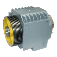
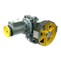
The DAF290 machine is delivered fully mounted and aligned on the machine
base frame (with double wrap including rope pulley). The base frame is set up
depending on the customer on the machine room floor or directly in a cement
floor.
In order to comply with regulations for noise abatement and sound
transmission, insulation elements are to be inserted between the frame
supports and the ground. These differ according to the type of mounting:
a) Rubber block 100 x 100 x 50 high without support
Fo
r mounting the machine on the machine room floor without a cement
floor or directly surface mounted on the cement floor.
b) Rubber block same as a), but with an additional base 140 x 140 x 80 mm
high, for mounting on a cement floor, support cast in cement floor.
(Coating thickness ≤ 60 mm.) The support is also to be cemented in place.
The number of rubber elements is based on the total weight load. The
required individual load should be between 7000 and 12 000 N / per element.
On arrangement of the supports, it is to be taken into account that the overall
centre of gravity lies within the rubber elements.
You will find the versions and dimensions of the machine base frames in the
order drawing.
Aligning the machine base frame
The machine is to be set up according to the plan of installation (drawing).
The rope departure from the traction sheave and deflecting pulley is to be
aligned plumb according to the drawing on the elevator car rope pulley or the
counterweight pulley. With load applied to the ropes, the machine should be
aligned horizontally on its installation surface. Irregularities are to be
balanced out by inserting shims under the support.
Rope arrangement
The
arrangement of the carrier cables in the suspension plate, on the traction
sheave as well as the cable rollers should be as symmetrical as possible.
Alignment of the machine on the base frame: The machine must be
aligned on the base frame in such a way that the axle alignment of traction
sheave and rope pulley (double wrap) are exactly parallel. The lateral
location of the rope grooves must be offset by half the groove gap dimension
(6 mm). The parallel dimension of the gap (ASL) of the outgoing ropes must
be complied with.
Setting: The location of the axles and/or the dimension of the gap can be
changed by loosening the securing bolts of the machine on the base frame
and adjusting the lateral stop screws on the machine foot.
Note: After completion of the setting-up procedures, the mounting bolts must
be tightened to the prescribed torque. See table in the Appendix
Product has been
replaced