109
NA11 - Manual - 02 - 2009
INSTALLATION
Block circuits
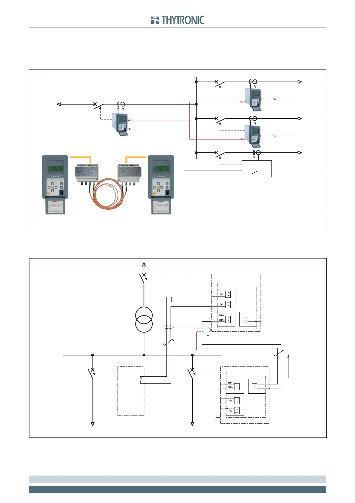
Block circuits may be connected to equipment located in a different switchboard: For the aim of
reliability, it is recommended to use conductors having a cross sectional thickness of at least 1 mm
2
and to not exceed 5 km in length. For connections that are particularly critical in terms of electro-
magnetic pollution, it is recommended to use BFO adaptor modules with fi bre optic connection.
When devices without committed pilot wire circuits must be embedded (devices other than Pro_N),
or in the event that further I/O circuits are need, output relays and binary inputs can be customized
to work in the logic selectivity system together with the committed pilot wire circuits.
A ring network example
[1]
is shown on the following pages.
Block out signals concerning the NA11 devices (S3.1, S3.2 e S3.3) are split on two isolated outputs by
means of MRB devices (B2.1, B2.2 and B2.3) to allow proper selectivity logic operation..
Nota 1 All diagram must be considered just as example; they cannot be comprehensive for real applications.
Block-sch.ai
Logic selectivity with BFO
BLIN1
BLIN1
BLIN1
Block2 IPh
BLOUT1
BLOUT1
TRIP I>>
TRIP I>>
TRIP I>>
TRIP I>>
Any device
Block-sch.ai
Logic selectivity with BFO
BLIN1
BLIN1
BLIN1
Block2 IPh
BLOUT1
BLOUT1
TRIP I>>
TRIP I>>
TRIP I>>
TRIP I>>
Any device
Block-misto.ai
Example for accelerated protection system with joint use of binary input and pilot wire links
BLIN1
BLOUT1
Uaux
BINARY INPUTS
A19
A20
A21
A22
BLOCK OUT
BLOCK IN
A17
A15
BLOUT-
BLOUT+
A16
A18
TRIP I>>TRIP I>>
START I>>
TRIP I>>
PRO_N
S1
S2 S3
PRO_N
BINARY INPUTS
A19
A20
A21
A22
BLOCK OUT
BLOCK IN
A17
A15
BLOUT-
BLOUT+
A16
A18
 Loading...


