86
86
NA11 - Manual - 02 - 2009
FUNCTION CHARACTERISTICS
Trip circuit supervision - 74TCS
Preface
The trip circuit can be monitored to signal possible anomalies that would lead to the missing opening
of circuit breaker when trip and/or operator command are issued.
Circuit interruption as well as missing of auxiliary voltage and/or coil faults are detected.
Supervision with one or two binary inputs can be select; depending on association of binary inputs,
the corresponding logic is automatically selected.
For this purpose the TCS1 and TCS2 (if two binary input are used) matching must be assigned to
the selected binary inputs inside the Set\Inputs\Binary input IN1 and Set\Inputs\Binary input IN2
menus.
When a binary input is programmed for the TCS function, the IN1 tON, IN2 tON, IN1 tOFF and
IN2 tOFF time delays must be reset to zero and the Logic parameter must be set to Active-ON
inside the Set\Inputs\Binary input IN1 and Set\Inputs\Binary input IN2 menus.
Operation and settings
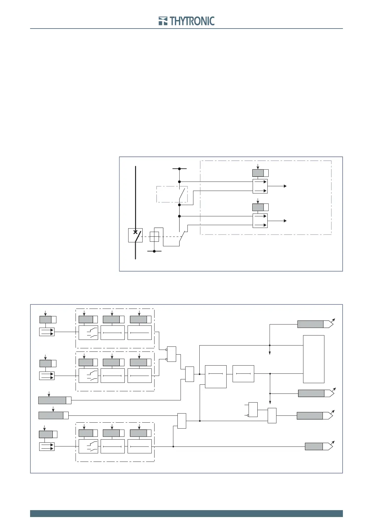
Two inputs supervision
With two binary input all malfunctions are detected (inclusive of mechanics faults).
The binary inputs are connected to the trip and to the 52b contacts.
The CB auxiliary voltage must be 36 V at least (twice the minimum threshold for every binary input)..
The faulty condition is detected occurs if both the following conditions are fi lled:
The TRIP contact is closed (external protection relay tripped);
The circuit breaker is closed (52a closed and 52b open))
Because such conditions can arise with healthy circuit too (e.g. a trip command is issued by the
protection relay but the CB opening time is still in progress), to avoid untimely operations the previ-
ous condition are checked every 80 ms and the output is issued after a 2 s delay; outputs are reset
A)
B)
TCS2s.ai
TRIP
+UAUX
Trip circuit supervision with two binary inputs - 74TCS
-UAUX
52a 52b
52
PRO-N
Binary input IN1
Binary input IN2
TCS1
TCS2
Towards 74TCS logic
Towards 74TCS logic
Fun-74TCS2.ai
0
2 s
T
0
0.6 s
T
&
&
Enable (ON≡Enable)
74TCS Enable
RESET
TRIPPING MATRIX
(LED+RELAYS)
Start 74TCS
Trip 74TCS
&
&
Block1 input (ON≡Block)
BLK1 74TCS
Block1
Start 74TCS 74TCS-ST-K
74TCS-ST-L
74TCS-TR-K
74TCS-TR-L
Start 74TCS
Trip 74TCS
Trip 74TCS
TCS1
TCS2
&
Enable (ON≡Enable)
74TCS-BLK1
Block1
T
Binary input INx
T0
Logic
INx
t
ON
INx
t
OFF
INx
t
ON
T0
n.o.
n.c.
INx
t
OFF
T
Binary input INx
T0
Logic
INx
t
ON
INx
t
OFF
INx
t
ON
T0
n.o.
n.c.
INx
t
OFF
T
Binary input INx
T0
Logic
INx
t
ON
INx
t
OFF
INx
t
ON
T0
n.o.
n.c.
INx
t
OFF
Logic diagram concerning the trip circuit supervision with two binary inputs - 74TCS