87
NA11 - Manual - 02 - 2009
FUNCTION CHARACTERISTICS
to zero if at least the A or B condition become false after 0.6 s delay.
[1]
The 74TCS element may be enabled or disabled; to enable it, the 74TCS Enable parameter must be
set to ON inside the Set\Profi le A(B)\Trip circuit supervision-74TCS submenu.
A logic block can be set from une binary input.
[2]
If the 74TCS-BLK1 parameter is set to ON, and a binary input is designed for logical block (Block1),
the TCS supervision function is blocked off whenever the given input is active. The trip timer is held
in reset condition, so the operate time counting starts when the input block goes down. The 74TCS-
BLK1 parameter is available inside the Set\Profi le A(B)\Trip circuit supervision-74TCS submenu.
All the parameters can be set separately for Profi le A and Profi le B.
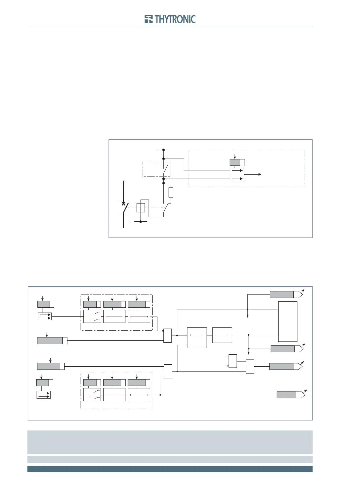
One input supervision
The binary input is connected to the trip and an external resistor must be connected the 52b auxiliary
contact.
The CB auxiliary voltage must be 36 V at least (twice the minimum threshold for binary input).
The fault condition of the trip circuit is detected by binary input power down.
With healthy circuit and TRIP contact closed, the binary input is feed across the 52a path (CB closed)
or across the resistor R and 52b path (CB open).
When the TRIP contact turns ON, the binary input becomes short-circuited; to avoid untimely opera-
tions the previous condition are checked every 80 ms and the output is issued after a 40 s delay in
order to allow the fault clearing and the consequent reset of the TRIP protection.
Outputs are reset to zero after 6 s from the TRIP contact open.
Note 1 Following assumption are considered for the framework:
Logic: ON,
Timers t
ON
and t
OFF:
reset to zero
TRIP contact of the protection: DE-energized, No latched
Note 2 Since two binary inputs are just used (TCS1 and TCS2), an external I/O module is required for the logic block function
TCS1s.ai
TRIP
R
+UAUX
-UAUX
52a 52b
52
PRO-N
Binary input INx
TCS1
Towards 74TCS logic
Trip circuit supervision with one binary inputs - 74TCS
Fun-74TCS1.ai
0
40 s
T
0
6 s
T
&
Enable (ON≡Enable)
74TCS Enable
RESET
TRIPPING MATRIX
(LED+RELAYS)
&
&
Block1 input (ON≡Block)
Block1
Start 74TCS
Start 74TCS
Trip 74TCS
Trip 74TCS
TCS1
&
Enable (ON≡Enable)
Block1
Binary input INx
T0
Logic
INx
t
ON
INx
t
ON
INx
t
OFF
T0
n.o.
n.c.
INx
t
OFF
Binary input INx
T0
Logic
INx
t
ON
INx
t
ON
INx
t
OFF
T0
n.o.
n.c.
INx
t
OFF
Start 74TCS
Trip 74TCS
BLK1 74TCS
74TCS-BLK1
74TCS-ST-K
74TCS-ST-L
74TCS-TR-K
74TCS-TR-L
Logic diagram concerning the trip circuit supervision with one binary inputs - 74TCS