115
NA11 - Manual - 02 - 2009
INSTALLATION
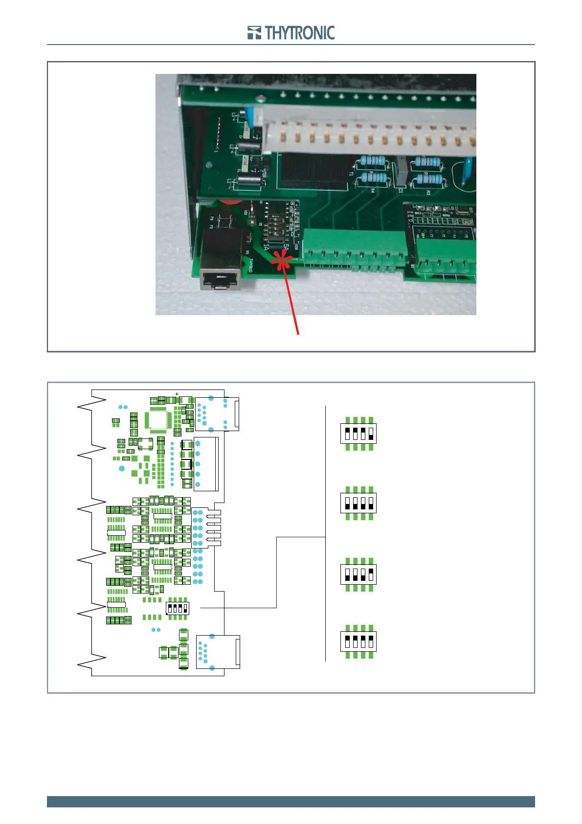
Move dip-switches according the following layout.
Reassemble all parts with the previous operations in reverse order.
Reconnect the RS485 and RJ45 cables (Ethernet and/or Thybus).
•
•
•
set-in-0.ai
Dip-switch localization concerning the nominal current setting inside the CPU board
set-in-0.ai
Dip-switch localization concerning the nominal current setting inside the CPU board
set-In.ai
Dip-switch localization concerning the nominal current setting inside the CPU board
Default settings:
- I
n
=5 A
- I
En
=1 A
Settings:
- I
n
=5 A
- I
En
=5 A
Settings:
- I
n
=1 A
- I
En
=1 A
Settings:
- I
n
=1 A
- I
En
=5 A
ETHERNET
THYBUS
485
1 A
5 A
S5
1 234
IL1
IL2
IL3
IE
1 A
5 A
S5
1234
IL1
IL2
IL3
IE
1 A
5 A
S5
1234
IL1
IL2
IL3
IE
1 A
5 A
S5
1234
IL1
IL2
IL3
IE
1 A
5 A
S5
1234
IL1
IL2
IL3
IE
 Loading...


