79
NA11 - Manual - 02 - 2009
FUNCTION CHARACTERISTICS
On to the committed pilot wire circuit (BLIN1 and BLOUT1) a full diagnostic is performed by means
periodic pulses that are sent by output circuit. If no pulses are received inside an adjustable window
at the selective block input circuit, a breaked pilot wire alarm is issued; the information is available
for reading (Breaked BLIN1 data inside Read \ Pilot wire diagnostic submenu) and can drive an
output relay and or a LED (PulseBLIN-K and or a PulseBLIN-L parameters inside Set \ Pilot wire
diagnostic submenu).
The control window may be programmed for OFF (no control) - 0.1 -1 - 5 - 10 - 60 - 120 s; the
Pulse BLIN1 parameter is available inside the Set \ Pilot wire diagnostic menu.
The same setting must be for output (see Output selective block).
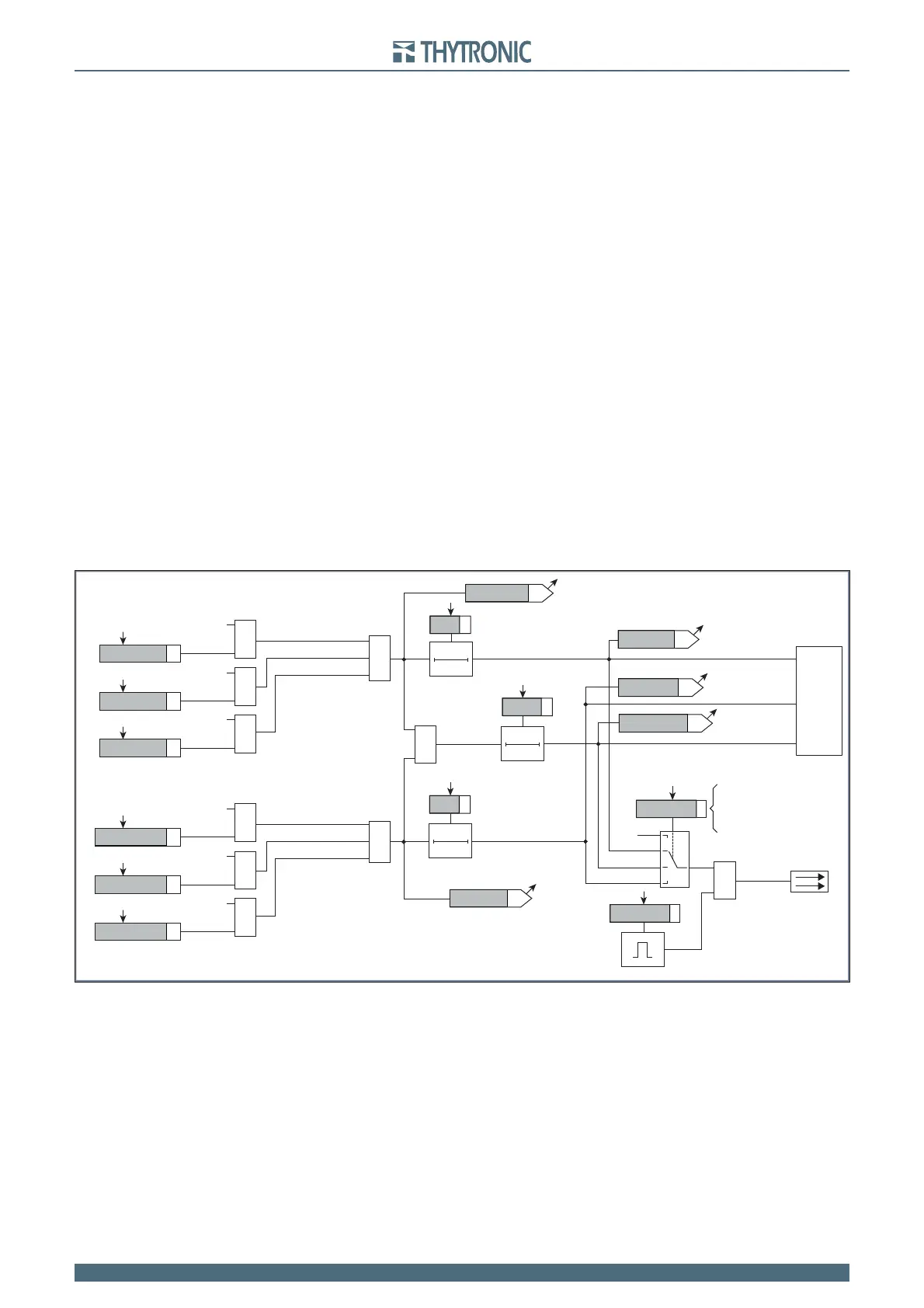
Output selective block
Use of output relay (K1...K6):
If the xxBLK2OUT, xxBLK2OUT and/or xxBLK2OUT parameters (enable) are set to ON and a
output relay is designed for selective block (Block2), the protection issues a block output by phase
elements (BLK2OUT-Iph) or by any protection element (BLK2OUT-Iph/IE), whenever the given start
(Start I>, Start I>> and/or Start I>>>) is active.
The BLK2OUT-Iph-K, BLK2OUT-Iph/IE-K and/or BLK2OUT-IE-K output relays must be set
inside the Set\Profi le A(or B)\Selective block-BLOCK2\ Selective block OUT menu; the same for ad-
dressing the LED indicators (BLK2OUT2-Iph-L, BLK2OUT2-IE-L and BLK2OUT2-Iph/IE_L).
When output relays are programmed for selective block output, the t
TR
time delays must reset to
zero; the operation mode must be set with self reset (No-latched inside Set\Relays submenu) and
the Logic parameters (Energized/De-energized) must be programmed in the same way of the
related binary input connected with-it.
Use of committed pilot wire output BLOUT1:
The output is a dry static relay.
The information about phase (ON IPh), earth (ON IE), or phase+earth (ON IPh/IE), block out may
be select programming the ModeBLOUT1 parameter inside the Set\Profi le A(or B)\Selective block-
BLOCK2\ Selective block OUT menu.
The parameters can be set separately for Profi le A and Profi le B
Operation
The output selective block goes ON at the same time of the xx element start; they hold steady (again
if the start reset to zero) for along the t
F-IPh
, t
F-IE
and
t
F-IPh/IE
adjustable times for phase, earth and
phase+earth functions.
The timers starts when one or more selective block function goes ON. When a timer expires, the
selective block output is disregarded (again if the start holds steady).
BLK2OUT-IPh-K
BLK2OUT-IPh-L
BLK2OUT-IPh/IE-K
BLK2OUT-IPh/IE-L
BLK2OUT-IE-K
BLK2OUT-IE-L
Block2-diagram.ai
Pilot wire output
TRIPPING MATRIX
(LED+RELAYS)
ModeBLOUT1
A
B
C
D
BLOUT1
≥1
≥1
≥1
t
F-IPh
t
F-IPh/IE
t
F-IE
ST-Iph BLK2
ST-IE BLK2
&
Block2 output
(ON≡Enable)
I>BLK2OUT
Start I>
≥1
T0
t
F-IPh/IE
T0
t
F-IPh
T0
t
F-IE
Blk2 OUT for I>
Blk2 OUT for I>>
Blk2 OUT for I>>>
BLK2OUT-Iph
BLK2OUT-Iph/IE
BLK2OUT-IE
&
I>>BLK2OUT
Start I>>
&
I>>>BLK2OUT
Start I>>>
&
IE>BLK2OUT
Start IE>
Blk2 OUT for IE>
Blk2 OUT for IE>>
Blk2 OUT for IE>>>
&
IE>>BLK2OUT
Start IE>>
&
IE>>>BLK2OUT
Start IE>>>
A = OFF
B = ON IPh
C = ON IPh/IE
D = ON IE
PulseBLOUT1
Pilot wire
Diagnostic
Schema funzionale relativo ai segnali d’uscita del blocco selettivo (Block2)
 Loading...


