FUNCTION CHARACTERISTICS
127
The first threshold trip (U>) may be inhibited by start of the second threshold (U>>) by setting ON the
U> Disabling by U>> start (U>disbyU>>) parameter available inside the Set \ Profile A (or B or C or
D) \ Overvoltage-59 \ U>> Element \ Setpoints menu.
Breaker failure (BF)
Each thresholds (U>, U>>) can be associated to BF protection by activating the relative parameter in
the matrices “Selection of function tripping for BF” in relevant BF menus
[1]
:
• Set \ Profile A (or B or C or D)\ Breaker failure
Note 1 The common settings concerning the Breaker failure protection are adjustable inside the Breaker Failure - BF menu.
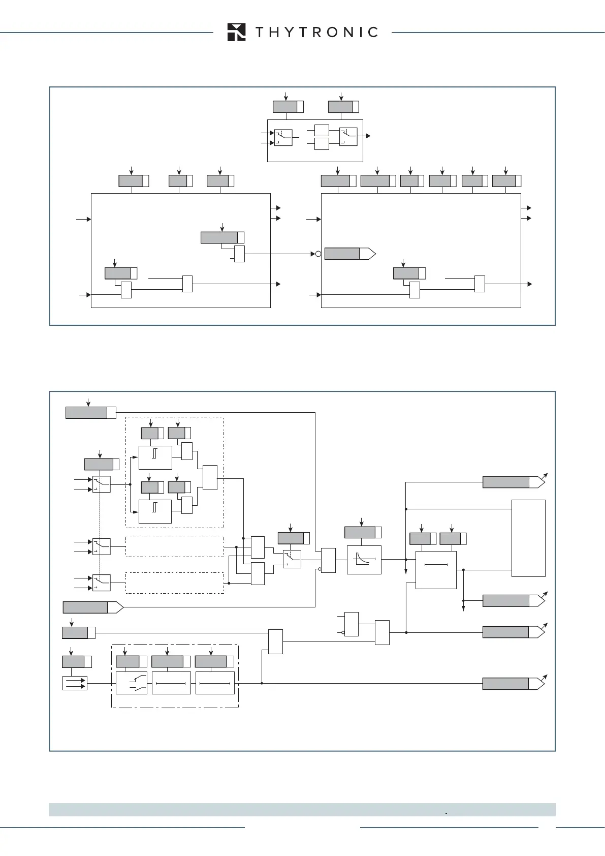
all-F59.ai
General logic diagram of the overvoltage elements - 59
U U
U> Element
U>> Element
Start U>>
Start U>>
Start U>
Trip U>
Trip U>>
&
U> disbyU>>
U> inhibition
t
U>
def
t
U>
inv
U>
def
t
U>>
def
U>>
def
U>
inv
U> Curve U> Enable State
Block1
BLK1U>
&
U>BLK1
Start U>
&
Block1
BLK1U>>
&
U>>BLK1
Start U>>
&
AND
U
12
,U
23
,U
31
U
U
L1
,U
L2
,U
L3
OR
Common configuration
Utype59
Logic59
Fun-F59_S1.ai
U> Curve
0T
RESET
t
U>
0T
TRIPPING MATRIX
(LED+RELAYS)
t
U>def
t
U>inv
Start U>
U>ST-K
Start U>
U>TR-K
U>ST-L
U>TR-L
Trip U>
Trip U>
BLK1U>
&
&
&
Enable (ON≡Enable)
Block1 input (ON≡Block)
U>BLK1
Block1
Block1
Binary input INx
T 0
Logic
INx
t
ON
INx
t
ON
INx
t
OFF
T0
n.o.
n.c.
INx
t
OFF
U> Inhibition
(ON≡
Inhibit
)
&
Logic59
≥1
&
Utype59
U
L1
U
12
U
L2
U
23
U
L3
U
31
≥1
&
State
U>
inv
U
≥
U>
def
U
≥
U>
inv
U>
def
&
State
ON≡Enable U> overvoltage element
U> Enable
Logic diagram concerning the first threshold (U>) of the overvoltage element - 59
XMR-T EQUIPMENT MANUAL
Ed. 2.9 - 02/2021

 Loading...