MEASURES, LOGIC STATES AND COUNTERS
173
— Selective Block - BLOCK2
The input and output state concerning the selective block are available (Read \ Selective block-
BLOCK2).
Block2 input
• Phase protections input selective block state BLK2IN-Iph ON/OFF
• Ground protections input selective block state BLK2IN-IE ON/OFF
• tB-Iph/IE Elapsed state tBtimeout ON/OFF
Block2 output
• Starting state of phase protections enabled
for external selective block on output ST-Iph-BLK2
ON/OFF
• Starting state of ground protections enabled
for external selective block on output ST-IE-BLK2
ON/OFF
• Phase protections output
selective block state BLK2-OUT-Iph ON/OFF
• Ground protections
output selective block state BLK2-OUT-IE ON/OFF
• Phase and ground protections
• output selective block state BLK2-OUT-Iph/IE ON/OFF
— Fault recording - SFR
Recording is triggered by one or more causes (up to 8 simultaneous):
• Activation (OFF-ON transition) of any relay programmed for trip of protection or control element
• External trigger (binary input programmed as Faulttrigger)
Twenty faults are recorded into a circular FIFO (First In, First Out) buffer.
[1][2]
— Event recording - SER
Recording is triggered by one or more causes:
• Start and/or trip of any enabled protection or control element
• Binary input activation (OFF-ON or ON-OFF transition)
• Power-on or power-down (Auxiliary power supply)
• Setting change.
One thousand events are recorded into a circular FIFO (First In, First Out) buffer.
[2][3]
Following information are stored in every record:
• Event counter
[4]
• Date and time
• Event cause (binary input/element trip/setting change)
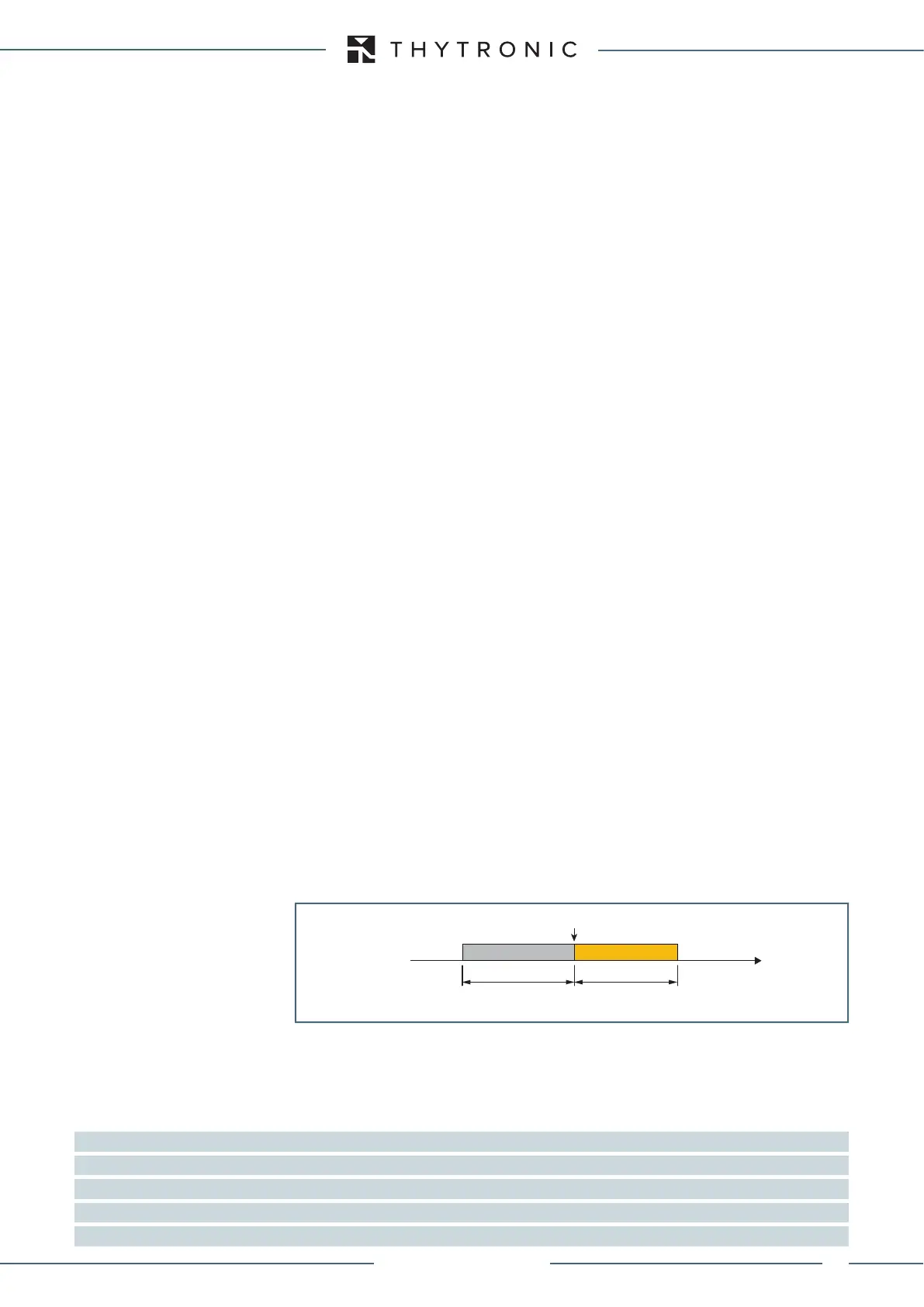
— Oscillography - DFR
Upon programmable trigger, the fault records are recorded in COMTRADE format; the sampled mea-
sures (24 sample per cycle) are stored in a circular shift memory buffer.
The fault record are self-triggered; they are stored in sequential order up the allocated memory is
used up after which the oldest memory is overwritten.
An operating procedure example for the digital fault recording is illustrated inside the Thyvisor
section.
Following parameters are user-programmable:
• Pre-trigger and post-trigger time
• Selected sampled quantities.
• Analog channels (1...12) allocation.
• Digital channels (1...12) allocation (output relay and/or binary inputs).
• Trigger setup; the information storage starts when a state transition on the selected signal occurs.
(protective element start and/or trip, output relay and/or binary input switching).
• Alarm: when the 80% of the buffer space is reached an alarm may be issued. The system being
of linear type, the records are back-to-back recorded to the end of available memory; the alarm
output is a warning in order that the user may download data
[5]
to clear memory for new records
COMTRADE
Records are recorded in COMTRADE format; (Common Format for Transient Data); This is a standard
for the data exchange for various types of tests or simulation datas, etc, for power system applica-
tions.
Note 1 Fault 0 is the newest fault, while the Fault 19 is the oldest fault
Note 2 Data are stored in non volatile memory; they are held in spite of power down
Note 3 Event 0 is the newest event, while the Event 299 is the oldest event
Note 4 Counter is updated at any new record; it may be cleared by means Thyvisor
Note 3 Data are stored into non-volatile memory; they are retained once power is turned off
trigger.ai
Disturbance Trigger
Trigger
Time
pre-trigger post-trigger
XMR-T EQUIPMENT MANUAL
Ed. 2.9 - 02/2021

 Loading...