184
INSTALLATION
For testing a PC may be directly connect to the XMR-D Ethernet port on the rear side.
With TX interface a cross cable must be employed, while an Ethernet-optical fiber converter, sui-
table for 100 Mb data rate must be employed if an FX port is implemented.
The link must be enabled by means Thyvisor sw and local connection:
• Set the IP address (HostIPaddress e IP net mask) in order that the XMR-T and PC parameters
are matched; the parameters are inside the Communication \ Ethernet submenu.
• Set to OFF the Autonegotiation parameter of device (Autonegotiationparameter inside Com-
munication \ Ethernet submenu).
Any change of the Ethernet communication parameters become active only after an hw reset
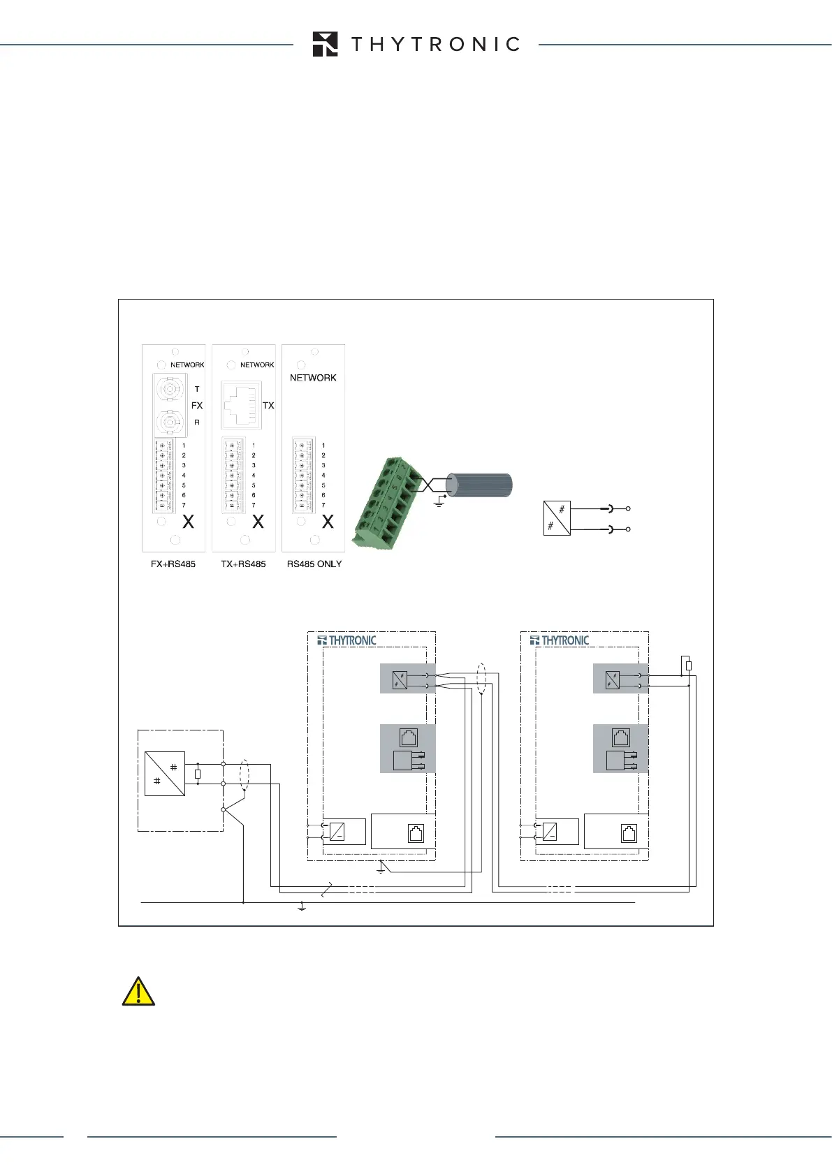
RS485 port
RS485 communication circuit connections must be made using screened twisted pair cable obser-
ving the polarities; screening must only be connected to the end terminating at the RS485 interface
circuit pertaining to the monitoring unit.
For RS485 connection longer than 5m or in environments particularly subject to disturbances due to
power transmission, the use of shielded cables is strictly recommended, with the shield connected
to earth on only one end.
RS485
120 Ω
120 Ω
SUPERVISION UNIT
A+
B-
RS485-wiring.ai
X7
X6
XMR-x
U
AUX
≅
ETH-1
ETH-2
ETHERNET
1 - DTR
2 - GND
3 - RX
4 - TX
RS232
RS485
A+
B-
X7
X6
XMR-x
U
AUX
≅
ETH-1
ETH-2
ETHERNET
1 - DTR
2 - GND
3 - RX
4 - TX
RS232
RS485
A+
B-
RS485
7
6
A+
B-
B-
A+
RS485
WARNING
XMR-T EQUIPMENT MANUAL
Ed. 2.9 - 02/2021

 Loading...