198
APPENDIX
L1 L2 L3
P1
S1
S2
P2
I
E1
P1
S1
S2
P2
I
E2
U
E
A
B
a
b
P1
S1
S2
P2
I
L1L
I
L2L
I
L3L
P1
S1
S2
P2
I
L1T
I
L2T
I
L3T
P1
S1
S2
P2
I
L1H
I
L2H
I
L3H
Z5
Z6
A7
A8
Z7
Z8
Z3
Z4
Z1
B7
B8
Z2
A5
A6
A3
A4
A1
A2
Y5
Y6
Y3
Y4
Y1
Y2
26
87T
74TCS
Nota 2
Nota 3
50N/51N
87NHIZ.2
50N.2/51N.2
74CT
64REF.2
50N/51N
SIDE L
87NHIZ.1
50N.1/51N.1
64REF.1
I2/I146
37
49 50/51
BF
50N/51N
SIDE T
I2/I146
37
49 50/51
BF
74CT
I2/I146
37
49 50/51
BF
74CT
SIDE H
SIDE TSIDE L
SIDE H
Nota 1
59N
24 27 59 81O 81U
SIDE H or SIDE L or SIDE T
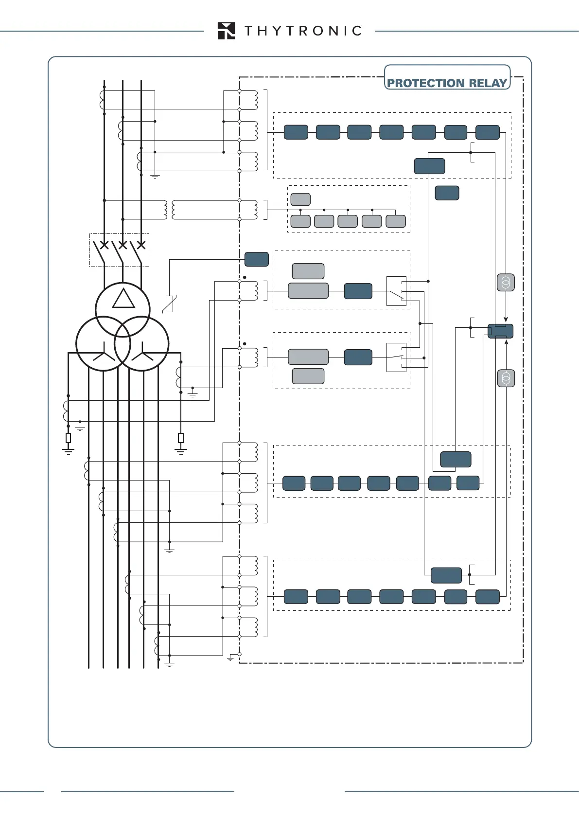
XMR-T
Note 1: 59N alternative to 24, 27, 58, 81O and 81U
Note 2: 50N.2/51N.2 alternative to 87NHIZ.2
Note 3: 50N.1/51N.1 alternative to 87NHIZ.1
Differential protection for three windings transformer
NOTE
- Incoming currents to the protected transformer must match to the the reference current inputs of the relay, with current direction leaving the
protected transformer must match current output from the current inputs of the relay.
- Incoming currents in the reference terminals of of the relay current inputs are considered positive, the outgoing negative.
- This convention applies to indicate the P1 CTs polarity toward the protected transformer.
XMR-T EQUIPMENT MANUAL
Ed. 2.9 - 02/2021

 Loading...