FUNCTION CHARACTERISTICS
45
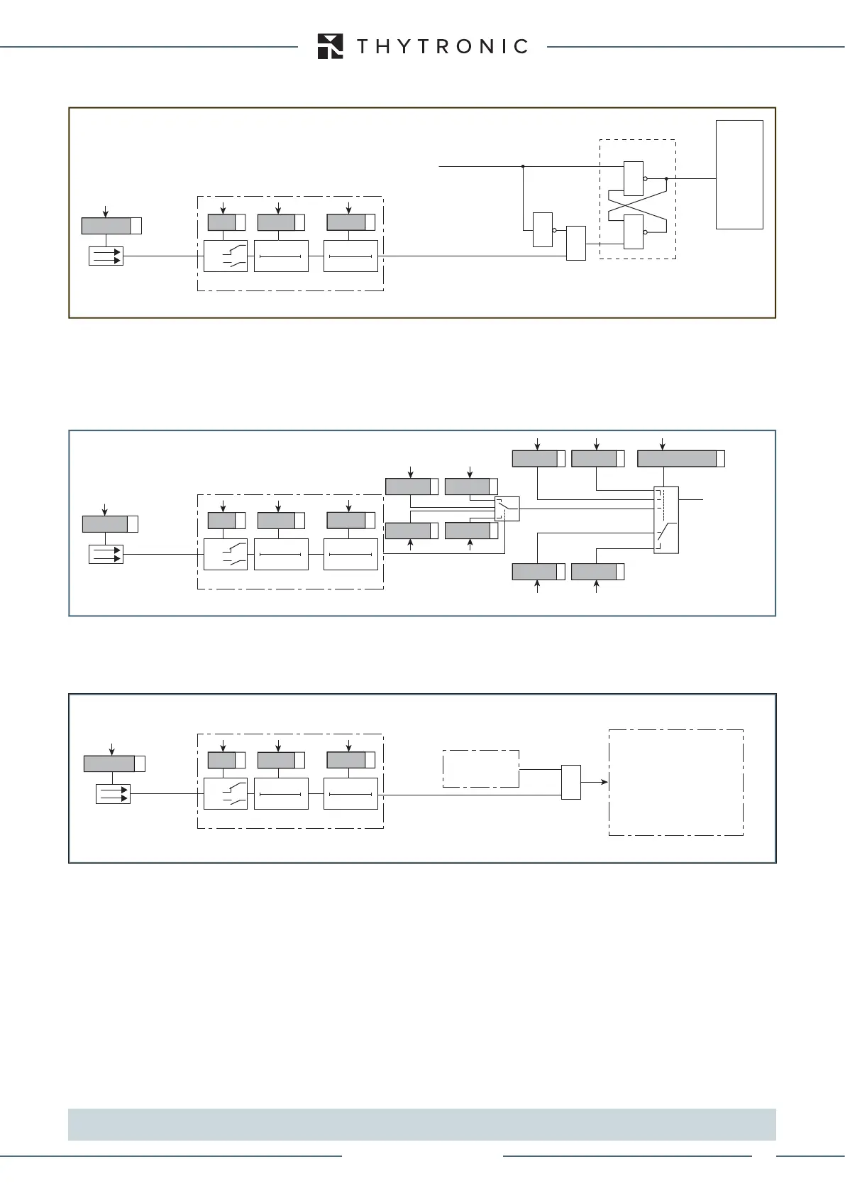
Reset LEDs
If the element tripped have gone back to rest condition, the latched LEDs and/or relays may be reset.
Set profile
Inside XMR devices, four independent setting profiles (A, B, C, D) [two (A, B) for XMR-D only] are
available. Whereas different settings are required, they are made in the setting profiles and stored
in the non volatile memory of relay. Applicable setting profile is activated usually via a binary input;
when the programmed input is activated, the profile B becomes operative as a replacement for the
default profile A or C or D and viceversa.
[1]
Fault trigger
When the programmed input is activated, a trigger is issued for fault record SFR). Data storing takes
place with the same procedure resulting from a trip of any protective elements.
Note 1 To enable the profile switching the “Input-selected” parameter must be set inside the “Profile selection” submenu.
If multiple setting groups are not required, Group A is the default selection
Reset-led.ai
TRIPPING MATRIX
(LED+RELAYS)
≥
≥
&
&
Set (ON≡turn on LED/relay)
S
Set-Reset latch
R
Reset (ON≡turn off LED/relay)
Reset LEDs
T 0
INx
t
ON
T0
n.o.
n.c.
INx tON
Logic
INx tOFF
INx
t
OFF
Binary input INx
Binary input allocation for reset signalling (LEDs)
Switch-profile.ai
(A, B, C, D
from binary input)
Binary input allocation for switching of setting profiles
Profile A
Profile B
Profile A
Profile selection
Profile B
Set profile
T 0
INx
t
ON
T0
n.o.
n.c.
INx tON
Logic
INx tOFF
INx
t
OFF
Binary input INx
Profile D
Profile C
Profile D
Profile C
Trigger-faults.ai
Binary input allocation for fault recorder trigger
Fault trigger
T 0
INx
t
ON
T0
n.o.
n.c.
INx tON
Logic
INx tOFF
INx
t
OFF
Binary input INx
Fault recording
Protection
element
I
L1
->I
L1r
I
L2
->I
L2r
.....
DTheta->DTheta-r
Inputs
Outputs
Fault cause info
≥1
XMR-T EQUIPMENT MANUAL
Ed. 2.9 - 02/2021

 Loading...