82
FUNCTION CHARACTERISTICS
Cold Load Pickup
If the CLP function (Cold Load Pick-up) is enabled for blocking 49, the thermal image is blocked for an
adjustable time interval, starting from the circuit breaker closure.
2
The operating mode parameter may be select by setting
ON-Elementblockingthe DThCLPMode
parameter inside the Set \ Profile A (or B or C or D) \ Thermal image-49LT \ Common configuration menu.
If the CLP function (Cold Load Pick-up) is enabled for threshold change, the equivalent thermal cur-
rent may be decreased by means a K
INR
factor for an adjustable time interval, starting from the circuit
breaker closure.
3
The operating mode parameter may be select by setting ON-Change setting
the DThCLP Mode parameter inside the Set \ Profile A (or B or C or D) \ Thermal image-49LT \
Common configuration menu.
The operating mode parameter may be select by setting
ON-Changesettingthe DThCLPMode pa-
rameter inside the Set \ Profile A (or B or C or D) \ Thermal image-49LT \ Common configuration menu.
La selezione del modo di funzionamento per la modifica della soglia è presente nel menù Set \ Pa-
rametri configurazione A(o B) \ Immagine termica - 49LT \ Configurazioni comuni programmando
ON-Modicasogliail parametro DThCLPMode.
Second harmonic restraint
For the Dth> threshold, a block from the second harmonic restraint may be set by setting ON the
DTh>2ndh-REST parameter inside the Set \ Profile A (or B or C or D) \ Thermal image-49LT \
Common configuration menu.
All elements can be enabled or disabled by setting ON or OFF the
DThetaAL1 Enable, DThe-
taAL2 Enable and/or DTheta>Enable parameters inside the Set \ Profile A (or B or C or D) \
Thermal image-49LT \ DthAL1 Element (DthAL2 Element, Dth> Element) menus>.
The trip element (Dth>) may be inhibited when a start of at least one of the overcurrent element
(50/51) is active, if the Dth>disby50-51 parameter is set ON inside the Set \ Profile A (or B or C or
D) \Thermal image-49LT \ Dth> Element menu.
The D
q
IN
parameter sets a minimum level of previous thermal image Dq
p
when the protection relay
is powered or when a remote (binary input) or local (keyboard or Thyvisor) command is issued.
The DthIN parameter may be adjusted inside the Set \ Profile A (or B or C or D) \ Thermal image-49LT
\ Common configuration menu.
To active the D
q
IN
preset value remotely, a binary input must be programmed as InitDTheta fun-
ction inside the Set \ Board 1(2) inputs \ Binary input IN1-1...(IN1-x) menus.
Breaker failure (BF)
Dth> threshold can be associated to BF protection by activating the relative parameter in the matri-
ces “Selection of function tripping for BF” in relevant BF menus
4
:
• Set \ Profile A (or B or C or D)\ Breaker failure
Note 4 The common settings concerning the Breaker failure protection are adjustable inside the Breaker Failure - BF menu.
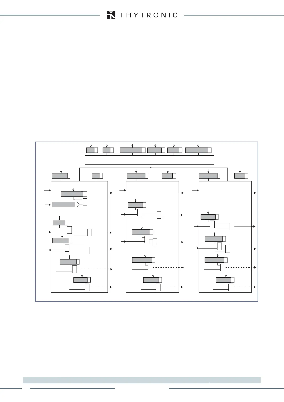
all-F49LT.ai
General logic diagram of the thermal image elements - 49LT
K
INR
T DthIN DthCLP Mode Dth2ndh REST tDthCLP
Common configuration
I
th
Dth> Element
Trip DTh>
DTh> Enable
DTh>
BLK4OUT
Dth>BLK4
Start I>
&
BLK2OUT
Dth>BLK2OUT
&
Trip Dth>
Trip Dth>
BLK2INDth>
Block2
&
Dth
>BLK2IN
&
DthAL1 Element
DThAL1
DThAL1
DThAL1
DThAL1 Enable
I
th
BLK4OUT
DthAL1BLK4
&
BLK2OUT
DthAL1BLK2OUT
&
Trip Dth>
Block1
BLK1DthAL1
&
DthAL1BLK1
&
Dth>AL1
DthAL1
BLK2INDthAL1
Block2
&
Dth
AL1BLK2IN
&
DthAL2
BLK2INDthAL2
Block2
&
Dth
AL2BLK2IN
&
DthAL2 Element
DThAL2
DThAL2
DThAL2 Enable
I
th
BLK4OUT
DthAL2BLK4
&
BLK2OUT
DthAL2BLK2OUT
&
Block1
BLK1DthAL2
&
DthAL2BLK1
&
Dth>AL2
Dth>AL2
Dth>AL2
Block1
BLK1Dth>
&
Dth>BLK1
Trip Dth>
&
&
50-51 inhibition
Dth>disby50-51
XMR-T EQUIPMENT MANUAL
Ed. 2.9 - 02/2021

 Loading...