96
FUNCTION CHARACTERISTICS
The second overcurrent element can be programmed with definite or inverse time characteristic
by setting the I> Time characteristic (I(H)>>Curve) parameter (
DEFINITE,I2t) available inside
the Set \ Profile A (or B or C or D) \ Phase overcurrent-50/51 side H \ I(H)> Element (I(H)>> Element,
I(H)>>> Element) \ Setpoints menu.
The trip of I(H)> element may be inhibited by the start of the second and/or third element (I(H)>>,
I(H)>>>) by setting ON the Disable I(H)> by start I(H)>>, Disable I(H)>> by start I(H)>>> (I(H)>di-
sbyI(H)>>,I(H)>disbyI(H)>>>) parameters available inside the Set \ Profile A (or B or C or D) \
Phase overcurrent-50/51 side H \ I(H)> Element (I(H)>> Element, I(H)>>> Element) \ Setpoints menus.
Similarly the trip of the I(H)>> element may be inhibited by start of the third element (I(H)>>>) by
setting ON the Disable I(H)>> by start I(H)>>> (I(H)>>disbyI(H)>>>) parameter available inside
the Set \ Profile A (or B or C or D) \ Phase overcurrent-50/51 side H \ I(H)> Element (I(H)>> Element,
I(H)>>> Element) \ Setpoints menu.
All the named parameters can be set separately for Profile A, B, C, D (Set \ Profile A (or B or C or D) \
Phase overcurrent-50/51 side H \ I(H)> Element (I(H)>> Element, I(H)>>> Element) \ Setpoints menus).
An adjustable reset time delay is provided for every threshold (t
(H)
>
RES
, t
(H)
>>
RES
, t
(H)
>>>
RES
).
Breaker failure (BF)
Each thresholds (I>, I>>, I>>>) can be associated to BF protection by activating the relative parame-
ter in the matrices “Selection of function tripping for BF” in relevant BF menus
[1]
:
• Set \ Profile A (or B or C or D)\ Breaker failure
Second harmonic restraint
For all overcurrent elements, a block from the second harmonic restraint may be set by setting ON the
I>2ndh-REST,I>>2ndh-REST,I>>>2ndh-REST parameters inside the Set \ Profile A (or B or
C or D) \ Phase overcurrent-50/51 side H \ I(H)> Element (I(H)>> Element, I(H)>>> Element) \ Setpoin-
ts menus.
Cold load pickup
If the CLP function (Cold Load Pick-up) is enabled for element blocking, the selected threshold may
be blocked for an adjustable time interval, starting from the circuit breaker closure.
This operating mode may be select by setting
ON-Elementblockingthe I(H)CLP>Mode,I(H)
CLP>>Modeand/or I(H)CLP>>>Mode parameters.
If the CLP function (Cold Load Pick-up) is enabled for threshold change, the selected threshold may
be changed for an adjustable time interval, starting from the circuit breaker closure.
This operating mode may be select by setting
ON-Change settingthe I(H)CLP> Mode, I(H)
CLP>>Modeand/or I(H)CLP>>>Mode parameters, whereas the operating thresholds within
the CLP may be adjusted inside the Set \ Profile A (or B or C or D) \ Phase overcurrent-50/51 side H \
I(H)> Element (I(H)>> Element, I(H)>>> Element) \ Definite time (Inverse time) menus.
For both operating modes the CLP Activation time parameters (
tCLP>,tCLP>>,tCLP>>>) may
be adjusted inside the Set \ Profile A (or B or C or D) \ Phase overcurrent-50/51 side H \ I(H)> Element
(I(H)>> Element, I(H)>>> Element) \ Setpoints menus.
For every of the three thresholds the following block criteria are available:
Logical block (Block1)
If the I(H)>BLK1,I(H)>>BLK1and/orI(H)>>>BLK1 enabling parameters are set to ON and
a binary input is designed for logical block (Block1), the concerning element is blocked off whenever
the given input is active.
[2]
The enabling parameters are available inside the Set \ Profile A (or B or C
or D) \ Phase overcurrent-50/51 side H \ I(H)> Element (I(H)>> Element, I(H)>>> Element) \ Setpoints
menus, while the Block1 function must be assigned to the selected binary input inside the Set \
Board1(2) inputs \ Binary input IN1-1...INx-x menus.
Note 1 The common settings concerning the Breaker failure protection are adjustable inside the Breaker Failure - BF menu.
Note 2 The exhaustive treatment of the logical block (Block 1) function may be found in the “Logic Block” paragraph inside CONTROL AND MONITOR-
ING section
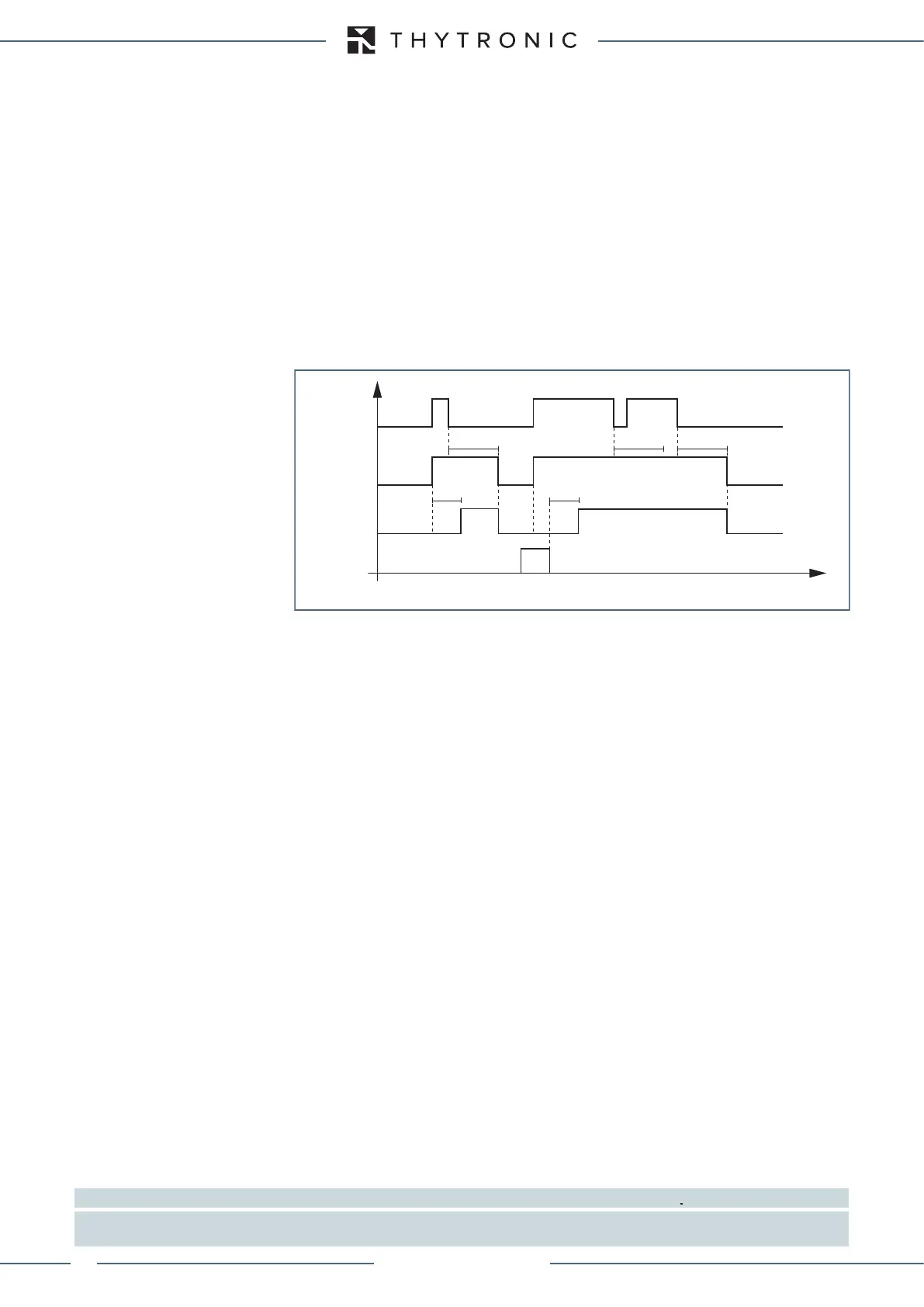
I> element phase overcurrent timers - 50/51 side H
Timers-F50-51.ai
I(H)> Start
I(H)> Trip
RESET
INPUT
t
(H)
>
RES
t
(H)
>
RES
t
(H)
>
RES
t
(H)
> t
(H)
>
t
XMR-T EQUIPMENT MANUAL
Ed. 2.9 - 02/2021

 Loading...