User Manual SDR-OMNI Avionics Test Set
Page 22 6 June 2023 Revision B
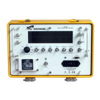
Table 3-2. Description of SDR-OMNI Indicators and Connectors
Receives the Wi-Fi Antenna.
Receives the GPS Antenna.
TNC female - Direct Connect port for direct connection to UUT or
to TAP-OMNI Antenna Coupler.
BNC female – Port for Telescopic Antenna connection for Over-
the-Air (OTA) testing of VOR/ILS/COMM radio/ELT.
Also used to connect to VSWR Return Loss Bridge
BNC female – Port for L-Band Directional Antenna for OTA testing
of ATC Transponders, UAT radios, and TCAS.
Receives the Micro USB Cable.
Receives the Headset connector.
Receives the DC Charger plug from the AC Power Adapter/DC
Charger.
Displays battery charge status: Amber = Charging; Green =
Charging complete
BNC female. Ch 2 Scope / TX Modulation "Q" input, 1 Mohm + 10
pF
BNC female. Ch 1 Scope / TX Modulation "I" input, 1 Mohm + 10
pF
15 pin HD connector - Receives Audio Test Cables (see Table 3-3
for connector pinout).
 Loading...