TECHNISONIC INDUSTRIES LIMITED
www.til.ca
TAF-550 Installation & Operating Instructions TiL 96RE187 Rev D
1-5
1.4 TECHNICAL SUMMARY
A summary of electrical, operational, mechanical and physical characteristics of the transceivers,
modular case and microphone indicated in Tables 1.1.
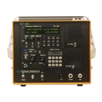
TABLE 1.1 TAF-550 MODULAR COMM SYSTEM - DATA SHEET
GENERAL:
Power Requirements:
AC Input Voltage/Current …………………………………………..….. 100 to 132 VAC @ 1.5 Amp
DC Input Voltage/Current (24V configuration ……………….... 2)1.6 VDC to 30 VDC @ 2.5 Amp
DC Input Voltage/Current (12V configuration) ….……………..... 1.6 VDC to 13 VDC @ 4.5 Amp
Frequency Range, TFM-138B (FM) ………………………….………………….. 138.000 to 174.000 MHz
Number of Channels (TFM-138B) ………………………….….... (120) programmable memory positions
Frequency Range, 91-DE (AM) ………………………………………………….. 117.975 to 138.000 MHz
Number of Channels (91-DE) ……………………………………………………………….. Ten (10) preset
Temperature & Humidity:
Operating Temperature Range ………………………………..….. -25°C(-13°F) to +55°C(+131°F)
Storage Temperature Range ………………………………….…... -55°C(-67°F) to +65°C(+149°F)
Relative Humidity ……………………………………………………………... 100% non-condensing
Microphone Compression Range ……………………….…….………………………………... 35 dB
Antenna:
Impedance ……………………………………………….…………………….…………..…..….. 50
VSWR …………………………………………………………….…………….…………..….. 4:1 MAX
Dimensions & Weight (excluding Front and Rear Covers):
Width X Height X Depth ……………………………………………….... 10.0 X 8.75 X 14.0 in MAX
Weight ……………………………………………………………………………………..... 16 lbs MAX
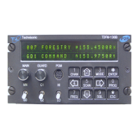
MODEL TFM-138B TRANSCEIVER:
TRANSMITTER:
RF Power Output …………………………….………………………………………….. 1 or 10 Watts
Output Impedance …………………………..…………………………………………….….. 50 ohms
Maximum Deviation …………………….….. ±5 kHz (25 kHz mode) or ±2.5 kHz (12.5 kHz mode)
Spurious Attenuation …………………..………………………………….…….. -90 dB below carrier
Frequency Stability (-20°C to +55°C) …….……………………………………….... ±0.0005% MAX
Microphone Circuit …………………………..………………………………..... Carbon or equivalent
Sidetone Output ……………………………..…………………………... 0.5W (max) into 600 ohms
Harmonic Attenuation ……………………..…………………………………….. -65dB below carrier
FM Hum and Noise ………………………..…………………………………..... -40 dB below carrier
Audio Input …...... 50 millivolts at 2.5kHz into 200 ohm input circuit for ±3.5kHz deviation, adjst.
Audio Distortion ……………………………………………………………………….……..... 5% MAX
MAIN RECEIVER:
Sensitivity (12 dB SINAD) ………………………………………………….... better than 0.35 μvolts
Adjacent Channel Selectivity
25 kHz Channel Spacing ………….………………………………………………….... -70dB
12.5 kHz Channel Spacing …………………………………………………………….. -70dB
Spurious Attenuation …………………………………………………………………………….. -90dB
Third Order Intermodulation …………………………………………………………………….. -70dB
Image Attenuation …………………………………………………………………………….….. -80dB
FM Acceptance …………………………………………………………………………………... ±6kHz
Hum & Noise ……………………………………………………………………………….... 50 dB MIN
Antenna Conducted Emission ………………………………………………………….. -70 dBm MIN
GUARD RECEIVER: All specifications identical to main receiver