TECHNISONIC INDUSTRIES LIMITED
www.til.ca
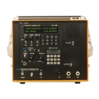
TAF-550 Installation & Operating Instructions TiL 96RE187 Rev D
3-3
TABLE 3.1 OPERATORS SWITCHES, CONTROLS AND INDICATORS - TAF-550
SWITCHES
CONTROLS &
INDICATORS
FUNCTIONAL DESCRIPTION
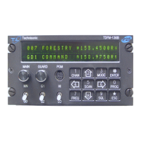
TFM-138B FM TRANSCEIVER - Switches, Controls and Indicators
1 MAIN Rx
VOLUME AND
POWER ON/OFF
A logarithmic potentiometer determines the Main Receiver audio level
applied to the internal TAF-550 speaker or headset when the transceiver is
operated in the receive mode. Also incorporates main power switch.
2 GUARD RX
VOLUME
A logarithmic potentiometer determines the Guard Receiver audio level
applied to the internal TAF-550 speaker or headset when the transceiver is
operated in the receive mode.
3 MAIN/GUARD
TRANSMIT
A toggle switch allows to TFM-138B Transmitter to operate on either the
main or guard transmit frequency.
4 G1/G2 SELECT Toggle switch selects one of the two guard channels.
5 HI/LO POWER
SWITCH
Toggle switch selects between 10 watts (HI) and 1 watt (LO) Transmitter RF
output power.
6 KEYPAD Performs channel selection, memory and function programming.
7 LED DISPLAY Two line 48 character alphanumeric message/frequency display indicates
information about the active main and guard frequencies including
transmit/receive, bandwidth and CTCSS tone/DPL code information.
8 MAIN/GUARD
SQUELCH LED
INDICATORS
Top squelch LED indicates when signal is received on main receiver.
Bottom squelch LED indicates when signal is received on the guard
receiver.
TiL-91-DE AM TRANSCEIVER - Switches, Controls and Indicators
9 POWER ON/OFF
SWITCH
A toggle switch applies the 27.5 volts nominal power supply to the 91-DE
transceiver. The transceiver is switched to ON in the toggle UP position the
transceiver is switched OFF in the toggle DOWN position.
10 POWER ON LED
INDICATOR
A GREEN LED Indicates when the POWER ON/OFF switch is set to ON
and voltage is applied to the 91-DE transceiver.
11 FUSE A 5 Amp FUSE protects the 27.5 volts nominal power supply line.
12 FUSE BLOWN
RED LED
INDICATOR
A RED LED indicates when the 5-Amp fuse is "blown", and External DC or
AC power is present.
13 SQUELCH
CONTROL
A linear potentiometer determines the squelch threshold level. When the
SQUELCH CONTROL is rotated in the counter-clockwise direction, the
SQUELCH GREEN LED indicates that the squelch is connecting
demodulated audio to the VOLUME control.
14 SQUELCH
INDICATOR
GREEN LED
A GREEN LED indicates the squelch circuit is connecting demodulated
audio signal to the VOLUME control.