Do you have a question about the Timeguard LED200PIRBE and is the answer not in the manual?
Ensure mains supply is OFF before installation/maintenance. Qualified electrician recommended. Check circuit load.
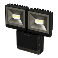
230V AC 50Hz, Class I earthed. 2x 10W LEDs (840lm). Energy: 20KWh/1000H. Detection: 10m range, 180° angle.
PIR sensor has defined detection zones at various vertical and horizontal angles.
Optimal coverage achieved with floodlight mounted at 2.5m height, requiring human body to cross zones.
Avoid heat sources and light sources in detection area. Reflective surfaces can cause false activation.
Ensure mains supply is switched off, circuit fuses removed, or circuit breaker turned OFF before starting.
Install an isolating switch for maintenance and to activate manual/auto override function.
Disconnect the back box from the luminaire by releasing the lugs on the left or right side.
Use back box as template, mark holes, drill carefully, insert rawl plugs, and pass cables through grommets.
Terminate 230V 50Hz mains supply into terminal block, ensuring correct polarity and sleeving of conductors.
Re-connect the luminaire to the back box, ensuring the 2 lugs latch firmly with a 'click'.
Connect 3-core mains supply cable to terminal block: Live to L, Neutral to N, Earth to Earth symbol.
Connect external load for slave lighting: Live to L1, Neutral to N, Earth to Earth symbol.
Set TIME ON to min, Lux to Sun. Power ON. Lamp illuminates during warm-up (30s), then extinguishes in Test Mode.
Unit operates day/night, illuminating for 2s per activation. Walk across zones to confirm detection pattern up to 10m.
Controls illumination duration after motion ceases, adjustable from 2 seconds to 30 minutes.
Determines darkness level for operation. Adjust clockwise (Sun) then slowly anti-clockwise until lamp illuminates.
Details pan/tilt adjustments with optional spacer and corner brackets for various coverage angles.
Switch wall switch twice (OFF/ON, OFF/ON) within 2s at night to illuminate continuously for 6 hours.
Switch wall switch once (OFF/ON) within 2 seconds to return to Auto Mode and normal operation.
Sticker masks areas for restricted detection (left/right) or to cover a smaller detection zone.
| Power | 20W |
|---|---|
| Motion Sensor Range | 12m |
| IP Rating | IP65 |
| Color Temperature | 4000K |
| Lumens | 1600 lm |
| PIR Detection Range | 12m |
| Colour Temperature | 4000K |
| Frequency | 50Hz |
| Weight | 0.6kg |
| Colour | Black |
| Luminous Flux | 1600 lm |
| Beam Angle | 120 degrees |
| PIR Detection Angle | 180° |
| Detection Angle | 180° |
| Operating Voltage | 220-240V |
| Material | Aluminium |