4
Switching DC loads or loads which use a different phase or
voltage supply from the AC mains – Voltage free Installation
(see diagram “H”)
Remove the factory fitted ‘bridge’ wire.
Connect the 3 core mains supply cable to the terminal block on the unit
block as follows:-
NEUTRAL (Blue) N
EARTH (Green/Yellow)
LIVE (Brown) L
Connect the load in series with the load supply between L
1
and L
2
terminals. Please note that the function of L
1
and L
2
can be viewed
as a simple switch controlled by the PIR sensor electronics.
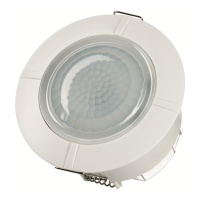
• When wiring is complete, it is recommended that the ceiling mounting
plate is fitted to the sensor body and fixed to the ceiling as follows:-
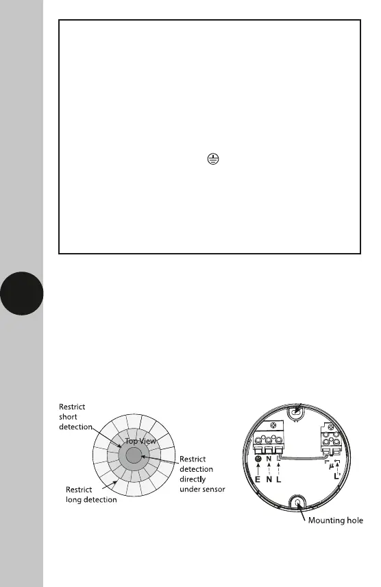
(See diagram ‘I’ for ceiling mounting assembly method.)
• Insert fixing screws through the sensor assembly into the wall plugs and
secure. Do not overtighten, if using a power screwdriver please ensure it
is set to a low torque setting so as not to damage the unit. Set the unit
Diagram C Lens Mask Diagram D