5
Diagram E Diagram F
Diagram HDiagram G
Diagram I
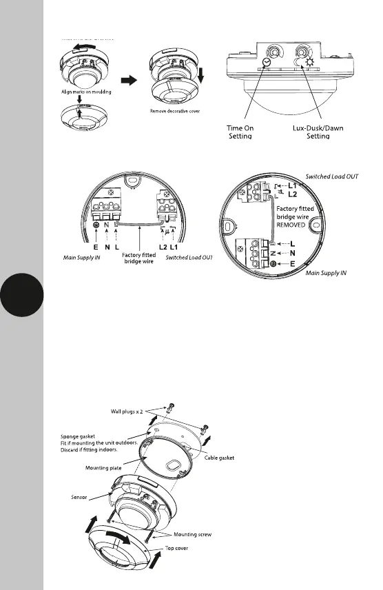
In the above illustration:
• 4 core cable may be used
• There is no external junction box
• A bridge is provided, pre-wired to
bridge across live supply from
AC mains to the output load
via the contacts.
In the above illustration:
• The L1 L2 terminals are used to
control a DC load or if the load
uses a different phase or voltage
supply from the AC mains in.
• Factory fitted bridge must be
removed to isolate L1 & L2
terminals from AC mains in.
 Loading...