5
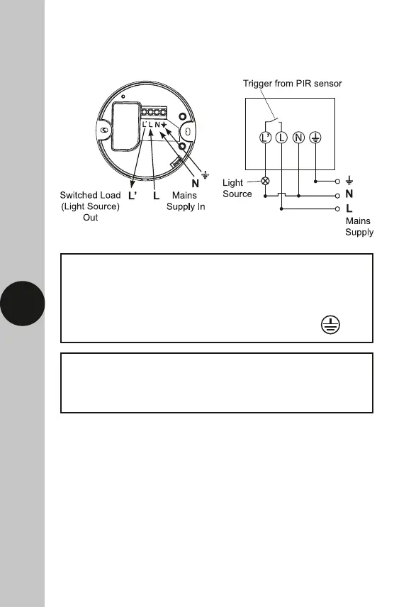
6. Connection Diagram
• Connect the cables as follows;
Switched Load (Light Source) Out
Switch Live (Brown or Red) to L1
Neutral Load (Blue or Black) to N
230V 50Hz Mains Supply
Live Supply (Brown or Red) to L
Neutral Supply (Blue or Black) to N
A ‘Loop Terminal’ is provided should a 3 core
cable be used which is marked