TPM 057 Version 1.0, May 31, 2018 Page | 6
OVERVIEW
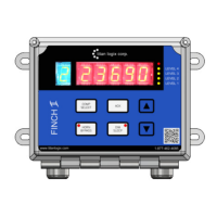
Figure 4 Finch II Display
Finch II Display
The Finch II Display is an external use, numeric display of volume information,
alarms, and system error codes from the TD100 transmitter. Various alarm
and error conditions are detected by the transmitter and display. These
alarm states control internal relays for alarm annunciation, high level
shutdown, and low-level prevention.
The Finch II contains high current relays to directly control a bottom loading
solenoid valve or control of an onboard loading pump. A weather-proof
junction box may be required to terminate alarm accessory wiring.
Refer to TPM 010 – Finch II Installation & Operation Manual.
5332INT In-Cab Display
The 5332INT In-Cab display is a numeric display of fluid volume (or level),
alarms, and system error codes from the TD100 transmitter. It is typically
mounted in the driver’s cab for convenience.
SensorLink
TM
The SensorLink
TM
software compiles strapping table information and,
together with inputs from the user, allows the user to set volume alarms and
track volume levels through the TD100 transmitter.
3.1.1 Optional Components
Gateway
The Gateway module transmits position and motion information of the vehicle
through a cellular connection, as well as gathering and transmitting data from
the TD100 and Finch II components.
Refer to TPM 053 – Gateway Installation & Operation Manual.
MIC 10
The MIC 10 is an interface device for connecting multiple TD100s to a third-
party Gateway or PLC system. Level, alarm and error information from the
TD100s is collected by the MIC 10 and forwarded to the connected device.
Rack Control Module (RCM)
The RCM is an accessory that enables secondary overfill prevention when
used with industry standard optic and thermistor terminal rack controllers.
The TD100 transmitter sends loaded volume, alarm states and detected
errors to the RCM.
Refer to TPM 007 – Rack Control Module Product Manual.
Figure 5 5332INT In-Cab
Display
Figure 6 Gateway Transmitter
Figure 7 MIC 10 Interface
Figure 8 Rack Control Module
 Loading...