TPM 057 Version 1.0, May 31, 2018 ii
4.2.2 Transmitter Installation ......................................................................................................... 34
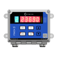
4.2.3 Finch II/5332INT Display Installation .................................................................................... 35
4.2.4 Accessories Installation (Optional) ........................................................................................ 35
4.3 Electrical Installation ...................................................................................................................... 35
4.3.1 Installation Wiring – System ................................................................................................. 36
4.3.2 Installation Wiring - Transmitter .......................................................................................... 37
4.3.3 Installation Wiring - Finch II Relays ....................................................................................... 38
4.3.4 Installation Wiring – 5332INT In-Cab Display ........................................................................ 39
4.3.5 Installation Wiring - Current Loop Option ............................................................................. 40
5 CONFIGURATION & CALIBRATION ................................................................................. 42
5.1 Transmitter .................................................................................................................................... 42
5.2 Finch II Display ............................................................................................................................... 43
5.3 Current Loop Transmitter (Option) ................................................................................................ 43
5.4 Start Up .......................................................................................................................................... 44
5.5 Offset Calibration ........................................................................................................................... 46
5.5.1 Method 1: Offset Calibration Using a Loaded and Metered Volume ................................... 46
5.5.2 Method 2: Offset Calibration Using an Unloaded and Metered Volume ............................. 46
5.5.3 Method 3: Offset Calibration Using a Measured Level ......................................................... 47
5.6 Spill Alarm Reset ............................................................................................................................ 47
5.6.1 Offset Calibration Method .................................................................................................... 47
6 TROUBLESHOOTING & MAINTENANCE .......................................................................... 49
6.1 Required Tools and Equipment...................................................................................................... 49
6.2 Error Codes .................................................................................................................................... 49
6.3 System Troubleshooting ................................................................................................................ 52
6.4 Current Loop System (Option) ....................................................................................................... 56
6.5 Repair ............................................................................................................................................. 57
6.6 Maintenance .................................................................................................................................. 57
7 REFERENCE DRAWINGS ................................................................................................. 58
 Loading...