7
11. “C” value is 139mm.
12. “D” can be measured from the gate easily.
13. “A” = “C” + “D”
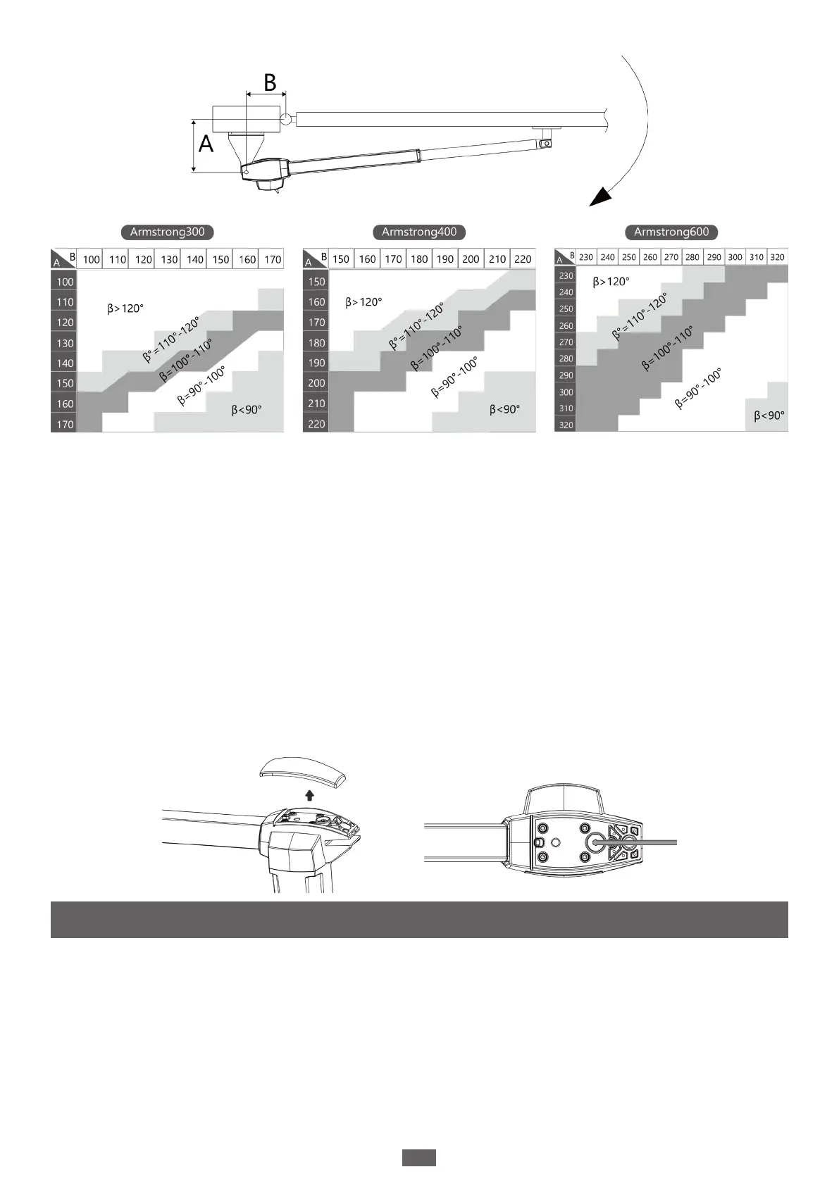
14. The value of “B” can be calculated from the value of “A” and the leaves opening angle.
Ex. If “A”=180-190mm with the leaves opening angle of 100 degrees, then the value of “B”
is approximate 190mm.
1. Remove the upper cover of the motor.
**Please make sure “B” and “A” are similar or the same in value that the leaves can be
operated smoothly , also to reduce the burden of the motor.**
• Release Gear
• Open Inward
2. Turn the release axle with a hex key to release
the motor.
3. The inner tube can be moved inward or outward.
4. Turn the release axle to engage the gear.
2. Installation Of The Motors
1. Choose the correct dimensions of the motors and position to be installed.
2. Check if the mounting surface the brackets to be installed is smooth, vertical and rigid..
3. Arrange the cable conduit for power supply cable of the motors.
4. Loosen the screw and remove the cover of the motor . (Figure1)
5. Place the leaves in the closed position.
6. Refer to the distance of “B” on page 6 ,place the rear plate in the correct position on the
mounting surface.
 Loading...