This unit has two inputs for PLUG-IN MODULES and a program
input.
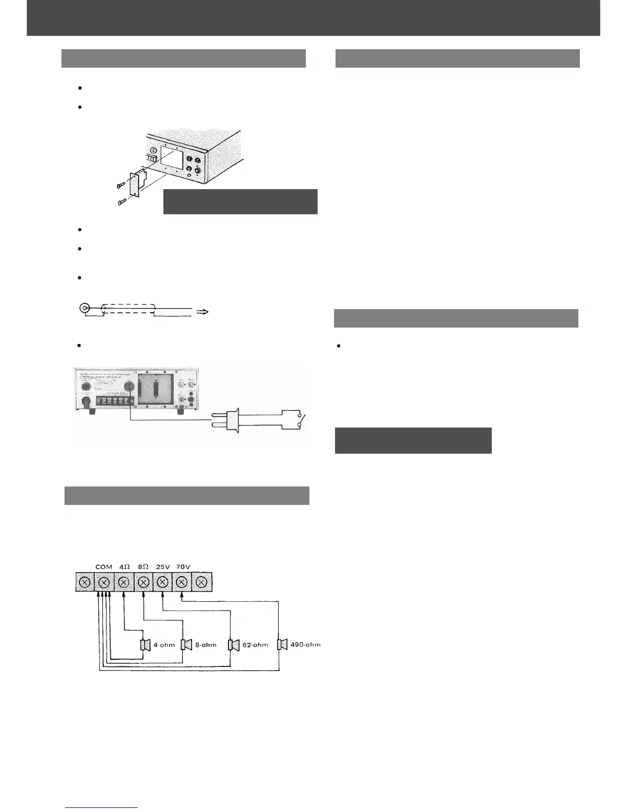
Plug the modules into INPUT PORTS, sliding them between the
guide rails, and secure each with two screws.
When not all INPUT PORTS are occupied, cover the vacant
PORTS with blank panels, and secure them with screws.
INPUT MODULES are provided in the following:
H-01
,
H-02,
H-03,
E-01,
X-01
,
B-01,
L-01,
S-01,
S-02,
S-03
* See PLUG-IN MODULES for details.
PROGRAM INPUT CONNECTION
RCA Phono Plug
Hot
Shield
Earth
Input source such as tape
recorder or SCA tuner
MUTE SWITCH CONNECTION
Connect a remote switch for MUTING to the MUTE TERMINAL.
Output transformer taps provide connections for 4-ohm and 8-ohm
speakers, plus 70-volt (490-ohm) and 25-volt (62-ohm) speaker dis-
tribution outlets. Class 2 wiring may be used. Connect to the
terminal of desired impedance and terminal COM (common).
Note: Impedances indicated above imply total speaker
system impedances.
- 2 -
When all connections are completed, turn power switch on. The
POWER INDICATOR (LED) lights green.
ADJUSTMENT OF VOLUME
Adjust the individual input volume controls to obtain the desired
operating level for respective inputs. If the output level is excessive,
the MAX OUTPUT INDICATOR (LED) will momentarily light, in
which case the gain of corresponding input should be reduced until
this light no longer goes on.
ADJUSTMENT OF TONE QUALITY
The tone quality of INPUT #2 is unadjustable but that of INPUT
#1 and PROGRAM INPUT is adjustable.
Adjust the tone quality using the BASS and TREBLE CONTROLS
(preadjustable) on the rear panel. Each of the controls provides
frequency-response characteristics of boost and attenuation. Normal
or flat response is obtained at center position. Turn CW to boost
response.
Do not block the cover ventilation holes.
The A-901 A should not be placed in areas;
1
2
3
4
5
with poor ventilation.
exposed to direct sunlight.
with high ambient temperature or adjacent to heat-generating
equipment.
with high humidity or dusty levels.
susceptible to vibration.
MUTE
TERMINAL
EARTH
Remote switch
Input Connections
Operation
Output Connections
Installation
CAUTION
Modules should not be inserted or
removed while the A-901 A is turned on.
CAUTION
Do not remove the case, or you may en-
counter an electric shock.