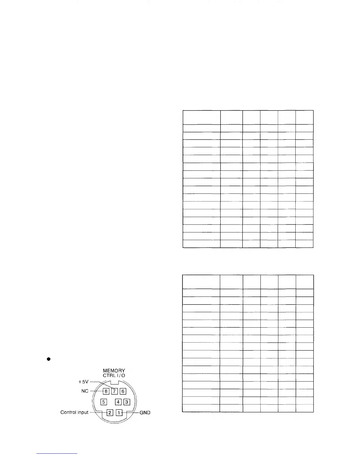
8. USING THE MEMORY I/O CONNECTOR
The memory I/O connector allows remote control of 16 pattern memories from external equipment, as well as
output of the memory selection status to external equipment. The I/O controls are performed in 4 bits. Remote
operations can be controlled using a make contact, and a 5V logic output is used to output information to
external equipment. By using this terminal, stored information can be remotely recalled or control signals can be
sent to other equipment.
Table 1 Pin's input status VS. memory number
8- 1. Remote memory call
Keeping the level of pin No. 2 low enables external
remote memory control. Table 1 shows the
relationship of each pin's input status to memory
number. Set patterns can be recalled through a
simple diode matrix.
Note No connection is possible for the pins in "H"
status shown in Table 1. (These pins are
pulled up at 5V.)
8-2. Memory selection status output
Table 2 Selected memory VS. pin's output status
The memory selection status can be output to
external equipment by making the connector's pin
No. 2 a high level. Table 2 shows the relationship of
selected memory to each pin's output status.
Note No connection is possible for the pin 2 (CTRL
input) shown in Table 2. (This pin is pulled up
at
5V.)
Pin arrangement of the memory I/O connector
Memory No. 1
Memory No. 2
Memory No. 3
Memory No, 4
Memory No. 5
Memory No. 6
Memory No. 7
Memory No. 8
Memory No. 9
Memory No. 10
Memory No. 11
Memory No. 12
Memory No. 13
Memory No. 14
Memory No. 15
Memory No. 16
PIN 2
CTRL IN
L
L
L
L
L
L
L
L
L
L
L
L
L
L
L
L
PIN 6
IN
L
L
L
L
L
L
L
L
H
H
H
H
H
H
H
H
PIN 5
IN
L
L
L
L
H
H
H
H
L
L
L
L
H
H
H
H
PIN 4
IN
L
L
H
H
L
L
H
H
L
L
H
H
L
L
H
H
PIN 3
IN
L
H
L
H
L
H
L
H
L
H
L
H
L
H
L
H
Memory No. 1
Memory No. 2
Memory No. 3
Memory No. 4
Memory No. 5
Memory No. 6
Memory No. 7
Memory No. 8
Memory No. 9
Memory No. 10
Memory No. 11
Memory No. 12
Memory No. 13
Memory No. 14
Memory No. 15
Memory No. 16
PIN 2
CTRL IN
H
H
H
H
H
H
H
H
H
H
H
H
H
H
H
H
PIN 6
OUT
L
L
L
L
L
L
L
L
H
H
H
H
H
H
H
H
PIN 5
OUT
L
L
L
L
H
H
H
H
L
L
L
L
H
H
H
H
PIN 4
OUT
L
L
H
H
L
L
H
H
L
L
H
H
L
L
H
H
PIN
3
OUT
L
H
L
H
L
H
L
H
L
H
L
H
L
H
L
H
9