5
5-19
4st 4/5/6 2011
8) Disassembly of Power Unit
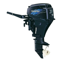
1. Place power unit on the work bench a.
2. Remove recoil starter 1 and flywheel cover 2.
3. Remove flywheel nut 3.
4. Remove flywheel 5 and key.
4
5
6
4
5
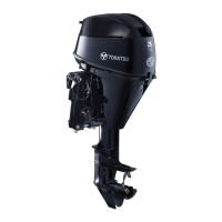
Apply forces to tools toward directions as
shown, and perform work taking care not to
allow flywheel holder to slip.
Flywheel Holder 4 : (Commercially use)
Flywheel Puller Kit 6 :
P/N. 369-72211-0
M6, L = 60mm, Bolts (3 pcs.)
(or recoil starter bolts and washers)
Apply forces to tools toward directions as
shown, and perform work taking care not to
allow flywheel holder to slip.
Flywheel Holder 4 : (Commercially use)
Flywheel Puller Kit 6 :
P/N. 369-72211-0
M6, L = 60mm, Bolts (3 pcs.)
(or recoil starter bolts and washers)
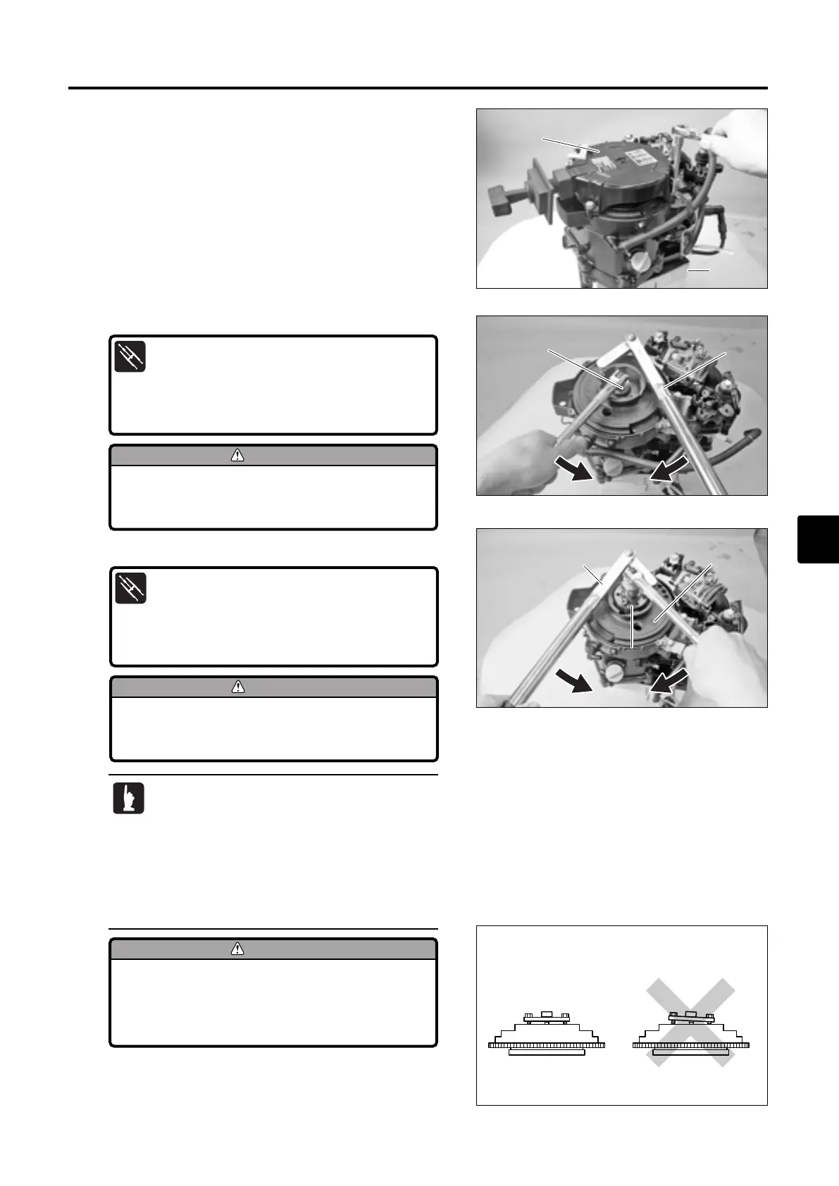
To prevent damages to engine and special
tools, tighten flywheel puller set bolts
evenly and keep flywheel puller parallel to
flywheel while working.
· Screw puller onto crank shaft end until flywheel
is disengaged from tapered section of crank
shaft.
· If bolts with specified size are not available,
use recoil starter bolts, or if they are deformed,
use new bolts.
· Set flywheel holder before attaching flywheel
puller.
MFS4-5-6Ech05110425.qxd11.4.2511:39AM ページ19
 Loading...