21
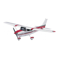
❏ ❏ 12. Using the marks inside the cowl as a guide,
use your rotary tool with a carbide cutter to cut a
rough, undersize starter hole in the cowl. See if
you can fi t the cowl over the engine. Continue fi tting
and cutting the cowl until you can get it into position
over the head and the cowl ring—cut only as much as
needed to get the cowl over the engine—fi nal cutting
and trimming will be done later after the cowl and
cowl ring have been permanently joined.
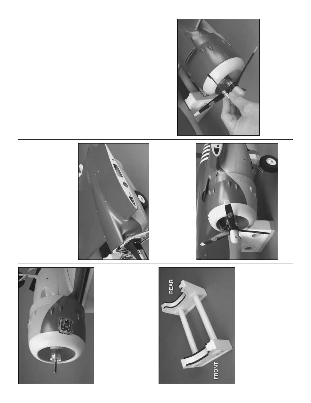
❏ ❏ 13. If you haven’t yet done so, assemble the
building stand that came with this kit by using epoxy
or white glue to glue the plastic tubes into the foam
cradles. Apply the foam cushion strips to the front and
back of both cradles where they support the fuselage.
❏ ❏ 14. Once you can get the cowl over the engine,
place the fuselage in the building stand. Then, fi t the
inboard wing panel to the fuselage with the aluminum
joiner tubes—no need to use the screws to secure
the tubes in the wing panel at this time. Counter-
weight made from bags of shot or something similar
will be needed on the tubes coming out of the right
side of the fuselage.
❏ ❏ 15. Use medium-grit sandpaper to roughen the
inside of the cowl all the way around where the cowl
ring will go.
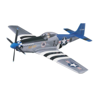
❏ ❏ 16. Test fi t the left, fi berglass carburetor
intake to the top of the wing. Make any adjustments
necessary for a good fi t. Then, drill 1/16" [1.6mm] holes
into the wing through the holes in the intake. Mount
the carburetor intake to the wing with eight #2 x 3/8"
[9.5mm] button-head Allen screws.
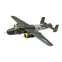
❏ ❏ 17. Trim the top of the cowl as necessary to
accommodate the intake. With the intake and cowl in
position, place a propeller on the engine and position
the cowl so it looks best—due to the out thrust and
down thrust of the engine, a compromise will have to
be made between centering the propeller in the cowl
and aligning the cowl with the nacelle cover—if the
propeller was centered in the front of the cowl, the
outward and downward angle of the cowl wouldn’t
look right. If the cowl were aligned perfectly with the
nacelle the propeller would be too far off center in the
cowl. Look at the cowl from different angles and get it
positioned where it looks best.
❏ ❏ 18. Once satisfi ed with the position of the cowl,
use medium CA and accelerator to tack glue the cowl
to the cowl ring in about four or six different spots.
❏ ❏ 19. Without accidentally breaking the cowl ring
free from the cowl, use your 3/32" ball-end hex wrench
to loosen the screws and carefully remove the cowl
from the nacelle. Use 30-minute epoxy mixed with
milled fi berglass or microballoons to securely glue
the cowl ring to the cowl with a small fi llet all the way
around both sides.
❏ ❏ 20. Cut a small, rounded slot in the top of the
cowl to accommodate the ball-end hex wrench to
access the top cowl mounting screw. Access through
this slot will be necessary after the replica engine has
been installed.
 Loading...