32
Refer to this photo while hooking up the rest of
the air system.
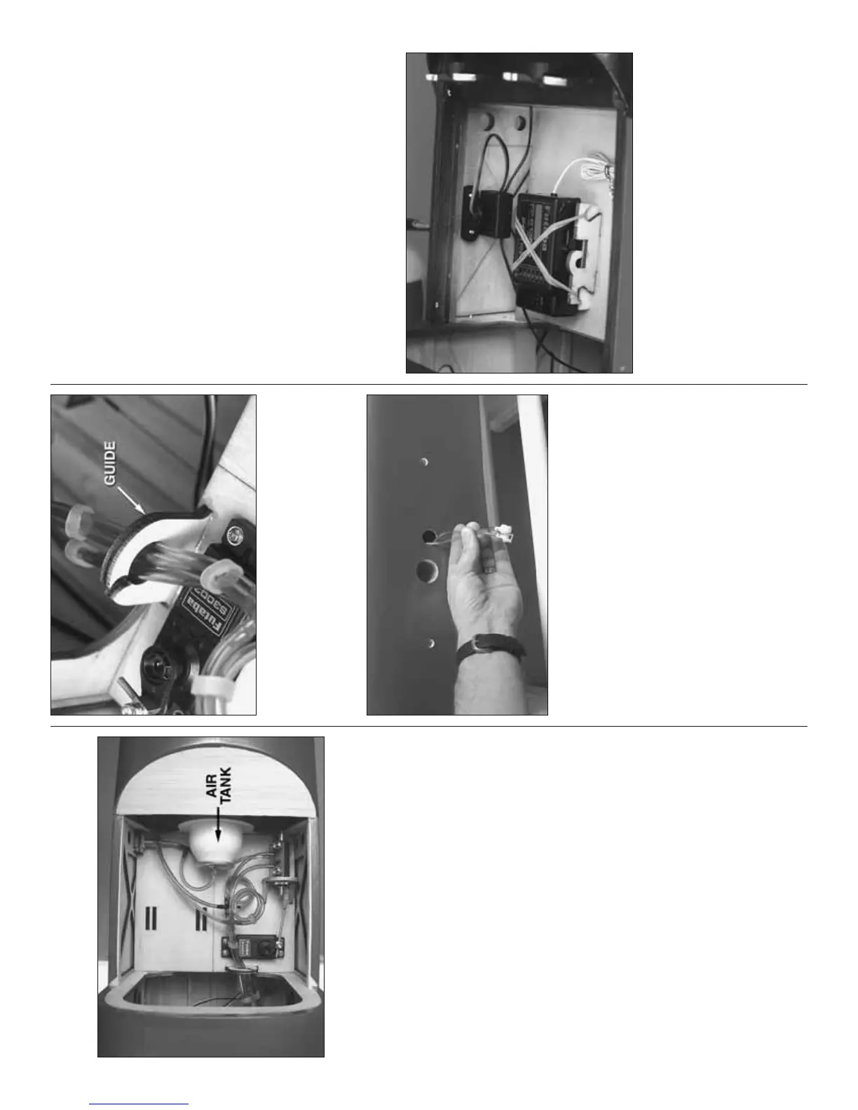
❏ 3. Connect approximately 2" [50mm] of air line
to the air tank that came with the retracts. Slide the
air tank into the holes in the front two formers in the
fuselage, but do not glue the tank in place yet.
❏ 4. Glue the air control valve mount to the radio tray.
Mount your retract servo. Then, connect the servo to
the valve with a 4" [100mm] pushrod cut to the correct
length, a nylon ball link and a screw-lock connector
on the servo with a nylon retainer and a 4-40 SHCS.
❏ 5. Cut the covering from the hole in the left side of
the fuselage for the air valve mount. Glue the fi ll valve
mount to the inside of the fuselage.
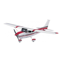
❏ 6. Use the remaining “T” fi ttings to connect the rest
of the air lines. Glue one of the plywood guides to
the radio tray for keeping the air lines and servo wires
organized. You can glue another guide to one of the
formers farther aft inside the fuselage.
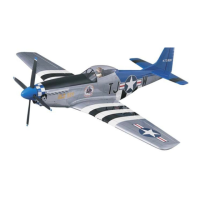
❏ 7. If you haven’t done so already, cut the covering
from the holes in both sides of the fuselage for the air
lines and servo wires to come out. Make sure the up
and down lines going back through the fuselage for
the main landing gear are long enough to come out of
the holes in both sides of the fuselage for connecting
to the lines coming from the inboard wing panels. Use
quick disconnects on the ends of the lines.
❏ 8. Use RTV silicone or epoxy to glue the air tank
into position—be certain the base, or front of the tank
(facing the front of the fuselage) does not protrude
more than 1/8" [3mm] forward of the front former.
Otherwise, it will interfere with the back of the scale
nose-gunner cabin.
One Final Note About Retracts: Test the retract
system either now, or later when you have completed
the rest of the radio installation. With all three landing
gears connected and operating, fi rst test the system
with the plane upside-down in the building cradle.
This will allow you to identify and trouble-shoot any
problems. Once the gear is working satisfactorily,
retest the system with the model upright in the stand.
Pressurizing the tank up to 120 psi. should allow for
two full cycles, but we have pressurized ours up to
140 psi. Use caution when using extreme pressure. If
the model sits in the sun for extended periods during
hot weather the lines can soften and pressure in the
system could rise.
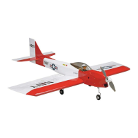
COMPLETE THE RADIO INSTALLATION
Refer to this photo while mounting the receiver
and switches.
❏ 1. Glue the plywood receiver mounts to the radio
tray to fi t your receiver. Mount the receiver with R/C
foam rubber and a couple of rubber bands.
❏ 2. Cut the sheeting on the outside of the fuselage
over the mounting locations for the receiver on/off
switch and an external charging receptacle. An Ernst
#124 Charge Receptacle is shown. Before mounting
the charge receptacle, slide the mounting back plate
over the battery charging wire coming from the on/off