33
switch, guide the wire through the mounting hole in
the fuselage, and THEN connect the charging plug to
the receptacle mount. Mount the switch and charge
jack to the fuselage.
❏ 3. Refer to the wiring diagrams in the back of the
manual for the servo extensions and Y-harnesses
used. Install and connect the wires as shown. Where
appropriate, secure connections between wires with
heat shrink tubing.
Throttle hookup: The wiring diagram for
connecting the throttle servos shows each servo
connected to separate channels in the receiver. They
are linked electronically through the transmitter,
but your receiver must also have an available
channel for this mix. For our Futaba radio we
connected one engine to channel 3 and the other
engine to channel 8 (Auxiliary 2). Depending on the
position of the assigned mixing switch, the throttles
can be operated separately (for synchronization
tuning and starting) or together with the throttle stick
during fl ight. However, if you do not have enough
available channels to link the throttles through the
transmitter, they could be linked with a Y-Harness
and connected to the same channel.
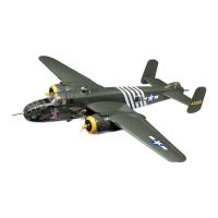
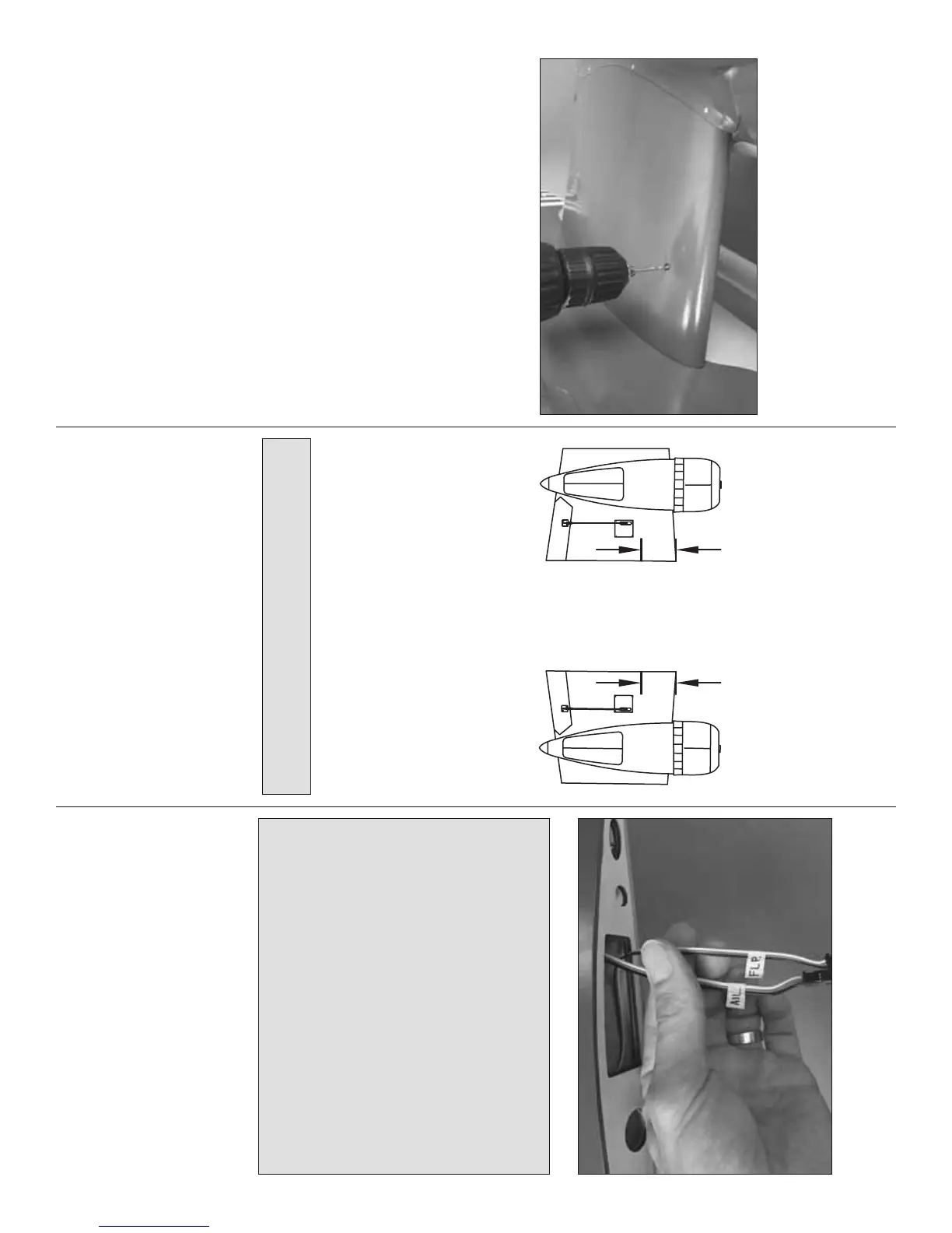
❏ 4. Mark the ends of all the servo wires that are
to be connected and removed during assembly and
disassembly at the fi eld with masking tape and a pen.
❏ 5. Guide the receiver antenna down through the
antenna tube in the fuselage.
❏ 6. Temporarily attach the inboard and outboard
wing panels and tail to the fuselage and connect all
the servo wires. Turn on the radio and make sure
everything operates correctly. Make any adjustments
necessary. Now would also be a good time to connect
the air lines, pressurize the system and operate the
retractable landing gear as well.
NOTE: The receiver battery pack will be mounted
after the nose-gunner cabin has been completed.
MOUNT THE INBOARD WING PANELS
We’ve already had the wings on and off the fuselage
a couple of times, but now it’s time to mount them
“for real.”
One end of the forward and aft aluminum wing tubes
is already drilled and tapped for 4-40 screws, but the
other end has to be drilled and tapped too.
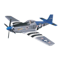
The balance point is 5" [127mm]
from the leading edge of the wing
where it contacts the fuselage.
5"
[127mm]
❏ 1. If you will not be balancing the model with a
Great Planes C.G. Machine, you will need to mark the
balance point on the bottom of the wing so you will
know where to lift the model when it’s time to check
the C.G. later. Now would be a good time to do this.
Use a fi ne-point felt-tip pen to mark the balance point
on the bottom of both inboard wing panels where they
meet the fuselage 5" [127mm] back from the leading
edge. There will be more information on C.G. and
balancing the model later after assembly has been
completed, but it’s a good idea to mark the balance
point now (if you won’t be using a C.G. Machine).
❏ 2. Fit either inboard wing panel to the fuselage
with the 30 x 440mm center main wing tube and both
10 x 305mm forward and aft main wing tubes. The
ends of the smaller tubes that have the threaded
holes should be inside the wing you are attaching to
the fuselage fi rst.
❏ 3. Turn and position the forward and aft tubes so the
threaded holes align with the holes in the wing panel.
If you cannot get both holes to align, try switching
tubes. If the holes still don’t align try switching wing
panels. If one of the tubes won’t go in quite far enough
to get the holes to align, it is okay to fi le the end of the
tube as necessary.
❏ 4. Once you have the holes in the tubes aligned
with the holes in one of the wing panels, thread 4-40 x
1" [25mm] SHCS into the wing panel and the tubes.
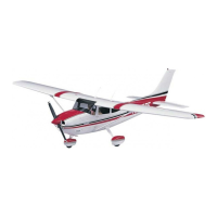
❏ 5. Tightly fi t the other inboard wing panel to the
fuselage and tubes. Using the holes in the wing panel
as a guide, drill #43 holes through both tubes.
❏ 6. Remove the panel. Use a fi ne-point felt-tip pen
to write on each tube which one is which and which
way goes up.
 Loading...