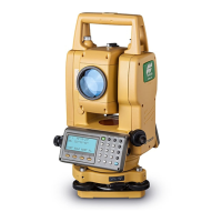
SPECIFICATIONS
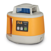
Rotating Laser
Accuracy : 2.0mm/20m (±20”)
Automatic correction range : ±3°
Operating range : Diameter Approx. 4m to 300m (When using LS-1)
Rotational speeds : 600r.p.m
Laser source : Laser diode (Visible, 635nm)
Laser output : 2.4mW
Safety standard for laser beam : CDRH (FDA) Class IIIa, IEC Class 3R
Power supply : 4 x C size dry cell batteries (alkaline)
Operating time : Approx. 60 hours at +20°C (+68°F)
Protection against water and dust : IP56 (Based on the standard IEC60529)
Operating temperature : -20°C to +50°C (-4°F to +122°F)
Dimensions : 167(L)x192.5(W)x189(H)mm (6.6 x 7.6 x 7.5 in)
Weight : 2.0kg [4.4 lbs] (Including dry cell batteries)
Level Sensor
Beam detection window : 45mm (1.78 in)
Beam detection precision : High precision: ±1mm (±0.04 in)/Normal precision: ±2mm (±0.08 in)
Beam detection indication : Liquid crystal (both sides) and buzzer
Power source : 1 x 9v dry cell battery
Operating time : Approx. 35 hours
Auto shut-off delay : Approx. 20 minutes without beam detection
Protection against water and dust : IP65 (Based on the standard IEC60529)
Operating temperature : -20°C to +50°C (-4°F to +122°F)
Dimensions : 135(L)x65(W)x24.5(H)mm (5.3 x 2.6 x 1.0 in)
Weight : 196g [6.9 oz] (including dry cell batteries)
[Checking]
1 Set up a tripod approx. 50m (160ft) from a wall. Mount the instrument on the tripod, facing the X1
side toward the wall.
2 Turn the instrument on and allow auto-leveling to complete.
3 Put the level sensor in fine detection mode by pressing the On-Grade precision switch.
4 By using the level sensor, mark the center position of laser beam on the wall. (X1)
5 Turn off the instrument.
Loosen the tripod screw, rotate the instrument 180 degrees and re-secure it on the tripod. The X2
side of the instrument faces toward the wall.
When rotating the instrument, avoid changing the height.
6 Turn the unit on again and allow auto-leveling to complete.
7 By using the level sensor, mark the center position of laser beam on the wall. (X2)
8 If the difference value of marked two laser beam heights (difference value of X1 and X2) are less
than 7mm, adjustments are not needed. The difference value is greater than 7mm, adjust the instru-
ment as described in right. *
9 Check the Y1 (handle) side as the same way.
*If the difference value is greater than 60mm (2 3/8 inches), contact your Topcon dealer.
CHECKS AND ADJUSTMENT
[To calibrate the X axis]
1 Face the X1 side of the instrument (panel side) toward a wall, press the Power switch while
pressing the height alert OFF switch.
Then the height alert OFF lamp will light, and manual mode ON lamp will blink.
2 Press the height alert OFF switch to calibrate the X axis. The manual mode ON lamp will light.
When auto-leveling finishes, the laser beam will emit.
3 Using the level sensor, mark the on-grade height of laser beam on a wall.
4 Rotate the instrument 180 degrees to face X2 side toward a wall.
5 In the same way as step 3, mark the on-grade height of laser beam on a wall.
6 By pressing the manual mode ON switch (laser beam moves up), or Power switch (laser beam
moves down), adjust the on-grade height of the beam until it is precisely centered between the
marks made in steps 3 and 5.
7 Press the height alert OFF switch to memorize the new laser beam calibration. The height alert OFF
lamp will blink. Power will shut off automatically when the calibration memorization is complete.
[To calibrate the Y axis]
1 Face the Y1 side of the instrument (handle side) toward a wall, press the Power switch while
pressing the height alert OFF switch.
Then the height alert OFF lamp will light, and manual mode ON lamp will blink.
2 Press the Power switch again. The auto leveling lamp will light.
3 Press the height alert OFF switch to calibrate the Y axis. The auto leveling lamp will light.
4 Using the level sensor, mark the on-grade height of laser beam on a wall.
5 Rotate the instrument 180 degrees to face Y2 side toward a wall.
6 In the same way as step 4, mark the on-grade height of laser beam on a wall.
7 By pressing the manual mode ON switch (laser beam moves up), or Power switch (laser beam
moves down), adjust the on-grade height of the beam until it is precisely centered between the
marks made in steps 4 and 6.
8 Press the height alert OFF switch to memorize the new laser beam calibration. The height alert OFF
lamp will blink. Power will shut off automatically when the calibration memorization is complete.
To discontinue calibration the instrument, press the Power switch while pressing the height alert
OFF switch.
When calibration is memorizing, if the height alert lamp continues to blink quickly and power does
not shut-off automatically, please contact your local Topcon dealer.
1 Set the instrument to the tripod or smooth surface.
2 Make sure instrument is roughly level.
3 Press power switch (ON).
4 Press power switch on level sensor (ON).
5 Select the precision mode by pressing the On-Grade precision
switch.
6 Locate the on-grade position "-------" or "====" by moving the level
sensor up and down.
7 Mark the position of On-Grade index.
(Top of the level sensor is 36mm [1 5/12"] from index for offset
marking.)
G
• TAURUS should be used with the level sensor (LS-1), a standard
equipment. We do not guarantee precision noted in this instruction
manual when used with other level sensors.
High precision mode
Normal precision mode
Battery remaining display
Lower than datum position
(Audio signal: High-pitch,
frequent beep sound)
Datum position
(Audio signal: Continuous
beep sound)
Higher than datum position
(Audio signal: Low frequent
beep sound)
OPERATION
Use the table below to determine operation errors indicated by blinking lamps on
the control panel. If corrective action listed does not correct error, please contact
your local Topcon dealer.
Lamp indication Error Cause Corrective Action
Lamp B, C and D blink in turn
Self-leveling range
error
The instrument tilt was too
large when set up.
Correct tilt of the instrument until it is less than 3°.
Lamp A lights
Battery power error Remaining battery power
is insufficient
Replace all 4 batteries at the same time.
Lamp B, C and D blink simultaneously
Tilt error Setup position of the in-
strument has changed
dramatically.
Turn power off, rough level the instrument, then turn power
on again. Check height of the laser beam as it may have
changed.
Lamp D blinks quickly
Calibration error Adjustable range exceed-
ed.
Repeat calibration procedure. If error repeats contact your
local dealer.
Lamp A, B, C and D blink simultaneously
Internal error Internal fault Turn power off, then on again.If error repeats contact your
local dealer.
36mm
ERROR DISPLAYS
1. Checking and adjusting calibration
Horizontal calibration of the laser beam can be checked by the user.
LS-1
http://www.topcon.co.jp
GLOBAL GATEWAY http://global.topcon.com/
Please see the following website for contact addresses.
How To Operate
Example Operational Height Alert Function
When the instrument system detects a shock, this function informs the
operator of it.
• When the instrument's installation status (height) is sharply changed
by the contact of the operator or the like, this function stops auto lev-
eling to keep the operation accuracy and informs the operator of the
situation. The three lamps blink at the same time as shown at the
right.
• After 1 minute has passed since the auto leveling function was acti-
vated and the laser beam was emitted, this function works.
• The height alert function does not work in the "Manual" mode.
Shock is given to
the instrument.
Height alert status
[How to reset]
1 Turn off the power switch.
2 Check whether the instrument is installed correctly.
3 Turn on the power switch. Auto leveling starts again. After auto lev-
eling is finished, the laser beam is emitted.
4 Make sure that the laser beam is set at the correct height. Then,
restart the operation.
The three lamps blink at the same time and
the rotary head rotates at low speed.
Buzzer sound ON/OFF display
X1 (panel side)
X2
Y1 (handle side)
Y2
D C B
A
X1
Level Sensor
Wall
Approx. 50m
X1 Laser beam
Laser point of X1
Approx. 50m
X1
X2
X2 Laser beam
2. Checking cone error
Perform the following check after completing horizontal calibration procedure.
[Checking]
1 Set up the laser centered between two walls approximately 40m (131ft) apart. Orient the instrument so one axis, either X or Y, is facing the walls.
2 Locate and mark the position of the rotating laser beam on both walls using the level sensor.
3 Turn off the instrument and move the instrument closer to wall A (1m to 2m /3 ft to 6 ft).
4 Do not change the axis orientation of the instrument. Turn the instrument on.
5 Again locate and mark the position of the rotating laser beam on both walls using the level sensor.
6 Measure the distance between the first and second marks on each wall.
7 If the difference between each set of marks is less than 4mm (5/32 of an inch), no error exists.
* If the difference value is greater than 4mm (5/32 inch), contact your Topcon dealer.
Cone error
Datum position
Wall A Wall B Wall A
Wall B
X1
31369 90040
 Loading...