Do you have a question about the Topcon GTS-600 Series and is the answer not in the manual?
Essential precautions for safe and proper handling of the instrument, covering operation, environment, and maintenance.
Explanation of safety displays and icons used in the manual to ensure user safety and prevent damage.
Detailed safety warnings and precautions, including risks of electrical shock, fire, and personal injury.
Defines the user requirements and necessary protective gear for operating the instrument.
Manufacturer's disclaimer regarding liability for misuse, damage, or loss of data due to product usage.
Information on the safety standards for the laser plummet type instruments and associated precautions.
Lists all the items included in the standard package when purchasing the GTS-600/600AF series.
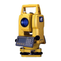
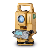
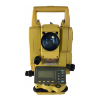
Identifies and illustrates the main parts and components of the GTS-600 series instrument.
Describes the instrument's display layout, including data fields, soft key functions, and display marks.
Details the function of each key on the instrument's operating panel for user interaction.
Explains the soft keys displayed at the bottom of the screen and their context-dependent functions.
Describes the functions accessible via the star key, including display adjustments and parameter settings.
Explains the automatic power-off function and how to set its time interval.
Details the automatic focusing feature for specific GTS-600AF models, including operation and adjustment.
Instructions for connecting external battery packs and power cords to the instrument.
Step-by-step guide for mounting the instrument on a tripod, leveling, and centering it precisely.
Procedure for turning on the instrument after confirming it is properly leveled.
Explains the battery status indicator and its meaning for measurement capability.
Overview of the main menu structure and the functions available via soft keys.
Details the automatic tilt correction for vertical and horizontal angles and its display.
Explains how to compensate for systematic errors like tilt, collimation, and datum offsets.
Describes the resume mode feature that memorizes the last display or mode when power is off.
Provides instructions for inputting alphanumeric characters for file names and other data.
Covers procedures for measuring horizontal and vertical angles, including zero setting.
Detailed steps for measuring horizontal and vertical angles of a target.
Explains how to switch between right (HR) and left (HL) horizontal angle measurement modes.
Describes how to set and measure angles based on a required horizontal angle using the HOLD function.
Details how to display vertical angles as percent grades (%) for specific measurements.
Covers distance measurement settings and modes, including atmospheric and prism constant corrections.
Instructions for setting atmospheric correction values based on temperature and pressure.
Guidance on setting the prism constant value for accurate distance measurements.
Explains how to perform continuous distance measurements and the associated display.
Details how to perform single or multiple (N-times) distance measurements and display average.
Describes the different distance measurement modes (Fine, Tracking, Coarse) and their characteristics.
Instructions for the stake-out function, calculating differences between measured and preset distances.
Covers setting occupied point coordinates and measuring unknown points in coordinate systems.
Procedure for inputting the coordinates of the instrument's occupied point.
Explains how to enter instrument and prism heights for coordinate measurements.
Details the process of executing coordinate measurement after setting occupied point and heights.
Describes how measurement results are transferred from the GTS-600 to a data collector.
Explains how to output measurement results using the REC soft key.
Program to compute backsight orientation angle using occupied and backsight point coordinates.
Stores coordinates of the next point after measurement for future use in orientation.
Calculates the vertical distance (height) of a remote object relative to a prism or ground point.
Calculates horizontal, slope, and vertical distances between two target prisms.
Accumulates horizontal angles to measure total angle and average angle for increased accuracy.
Assists in staking out points using coordinate values, with options for job management.
Routines for inputting, searching, and viewing coordinate data within jobs.
Features to find point numbers with coordinates and view stored job data.
Allows collection of coordinates via Side Shot or Resection methods.
Enables setting and modifying the grid factor for distance calculations.
Computes backsight angle orientation and guides layout of points.
Provides distance instructions for rod person and displays cut/fill information.
Measures height of inaccessible objects above points on a base line.
Allows loading application programs from a PC to the GTS-600 series.
Displays memory size, free memory, and battery expiration date.
Enables file protection, indicated by an asterisk, preventing deletion without removing protection.
Allows renaming of files stored in internal memory.
Erases a file from internal memory; protected files cannot be deleted.
Erases all files from internal memory; files cannot be retrieved.
Instructions for setting communication parameters like Baud rate for data transfer.
Procedure for transferring data files from a PC to the GTS-600 series.
Procedure for transferring files from the GTS-600 internal memory to a PC.
Overview of parameter settings for measurement, display, and communication.
Configuration options for angle units, tilt correction, error correction, and display settings.
Settings for communication parameters such as baud rate, data length, and parity.
Detailed instructions for configuring measurement and communication parameters.
Guides the user through setting measurement and display parameters like units and corrections.
Explains how to set communication parameters for data transfer.
Instructions for establishing, turning off, and changing the instrument's password.
Procedure to check and adjust the instrument constant for accurate measurements.
Method to verify if the EDM and theodolite optical axes are properly matched.
General guidance on checking and adjusting theodolite functions in sequence.
Procedure to check and adjust the plate level for perpendicularity to the vertical axis.
Procedure to check and adjust the circular level for perpendicularity to the vertical axis.
Describes how to adjust the vertical cross-hair to ensure it is perpendicular to the telescope's horizontal axis.
Explains how to collimate the instrument to make the line of sight perpendicular to the horizontal axis.
Procedure to check and adjust the optical plummet telescope for alignment with the vertical axis.
Guide for checking and adjusting the laser plummet for centering with the measuring point.
Details software-based compensation for systematic errors like tilt, collimation, and axis errors.
How to view constant lists and switch compensation systematic errors ON or OFF.
Instructions for adjusting the instrument's internal date and time settings.
Procedure to set the instrument constant value obtained from calibration.
Mode used for frequency testing, where the EDM beam is emitted continuously.
Instructions for setting the prism constant value, especially for non-Topcon prisms.
Presents the formulas for calculating atmospheric correction based on temperature and pressure.
Guides on setting temperature and pressure values directly or using a chart for correction.
Explains the distance calculation formulas incorporating refraction and earth curvature corrections.
Instructions for removing, charging, and refreshing the on-board BT-52QA battery.
Steps for detaching the instrument from the tribrach using the locking lever.
Steps for attaching the instrument to the tribrach, ensuring proper alignment and locking.
Details various battery chargers and packs compatible with the GTS-600 series.
Lists power cords and adapters required for charging and connecting the instrument.
Information on various prism units, holders, and cases for different measurement needs.
Describes the types of tripods available for instrument setup.
Includes items like eyepieces, compasses, reticles, filters, and tribrachs.
Details the specifications and charging information for the on-board BT-50Q battery.
Information on external battery packs, their specifications, and compatibility.
Overview of different battery chargers and their charging times for various battery models.
Illustrates how to arrange prisms and adaptors for different measurement purposes.
Description of the mini prism and its positioning capabilities.
Details various prism cases for storage and transport of prism units.
Shows tripods used for setting prisms at the same height as the instrument.
Guidelines for safely transporting the instrument to prevent damage from shocks or vibrations.
Important advice on handling, exposure to sunlight, temperature, and general usage.
Instructions for cleaning the instrument, lens surface, and case.
Warning against self-disassembly and advice to consult TOPCON or a dealer for issues.
Lists common error codes related to battery, AF, focus, and W/C OVER, with countermeasures.
Lists system errors for angle measurement, data transmission, and focusing, with required actions.
Technical details of the telescope, including length, magnification, field of view, and focus.
Details on measurement range, accuracy, least count, and display capabilities.
Information on electronic angle measurement method, detecting systems, and accuracy.
Details on the instrument's computer unit, including OS, memory, and calendar clock.
Specifications for the automatic focusing feature, including range and time.
Includes instrument height, level sensitivity, optical plummet, and laser plummet details.
Explains dual axis compensation for horizontal angle errors due to tilt.
Provides guidelines on proper battery charging, discharging, and storage for optimal service life.
| Telescope Magnification | 30x |
|---|---|
| Type | Total Station |
| Angle Measurement Accuracy | 5 seconds |
| Distance Measurement Range (without prism) | 500 m |
| Reflectorless Range | 500 m |
| Operating Temperature Range | -20°C to +50°C |
| Display | Dual-line LCD |