ISOBUS ARTEMIS - SEED DRILL CONTROLLER
5
1 Introduction
This manual provides basic operator instructions for both single-channel and multi-channel generic Isobus “Artemis” Seed
Drill Controller application. It also includes settings in the “Drill Setup” menu accessible by the operator. Information on
Technician and Factory level settings are not included in this manual.
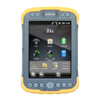
NOTE: Illustrations in this manual are based on a Topcon X25 terminal. The actual Artemis app screen display/button layout and
functions may vary slightly from those shown, depending on the specific implement being controlled, the UT the app is
being run on, its GUI and user-defined settings. If necessary, please refer to the manufacturers user manual for setup and
loading the Artemis app on other UT’s.
1.1 System Overview
The Artemis is an ISOBUS-compatible, monitoring and application control system for seed drills. It may be configured
with up to 4 control channels. Forward speed measurement and cutout sensing enables full proportional control, to
maintain (within limits) a set application of one or more products irrespective of changes in forward speed.
In its simplest application, the Artemis may be setup in a single-channel configuration to control a single motor as shown
in figure 1. Additional CAN modules enable multi-channel configurations for combined seed/fertiliser/pellet application
(including electro-hydraulic control), to suit a wide range of drill makes and models.
1.1.1 System Components
The system will vary depending on the drill make and model, but will be some combination of one or more of the
following,
The main electronic components are,
ISOBUS UT
ISOBUS ‘AS1’ ECU – the “brains” of the system, with the application software and object pool. It also includes the
interface for sensors and actuators.
Motor Control (MCM) CAN Module – CANBUS interface for a gearmotor and sensors.
Applicator Control (APM) CAN Module – CANBUS interface for an Applicator system (optional).
Connected via the Motor Control Module (‘MCM’) :
Gearmotor –driving either single or multiple metering units.
Shaft Speed Confirmation sensor(s) – a magnetic sensor that confirms that the motor is driving the metering unit. A
second sensor is optional.
Priming Switch – manually operates the metering motor to dispense product for calibration purposes.
Hopper Level Sensor(s) – An upper “pre-level” sensor provides an early-warning alarm, giving the operator advance
notice to refill. A lower sensor provides a second warning when the hopper is about to run out.
Connected via the ‘AS1’ ECU :
Area Cutout/Tramline Advance Switch / Lower Area Cutout Switch - one or two finger switches positioned to detect
when the drill is lowered/raised into or out of work. Can be configured to also provide the tramline advance signal.
Forward Speed Sensor –Speed signal sent from ISOBUS UT, or from a “Satspeed” device.
Fan Speed Sensor(s) - a magnetic sensor on the fan drive. A second sensor is optional.
Tramline mechanism (existing) – the solenoid or motor-type mechanisms are rewired to the AS1 ECU to be controlled by
the Artemis.
 Loading...