Do you have a question about the Topcon Liquid Systems CM-40 and is the answer not in the manual?
Lists physical installation, connection, and tank filling steps before liquid system configuration.
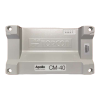
The Liquid Systems (SA) Rate Control Module with Topcon Apollo CM-40 ECU and EM-24 Expansion Module is designed for precise liquid application with section control, primarily used in agricultural seeding operations. This system facilitates the setup and control of a single liquid system, with the capability to expand for additional liquid channels.
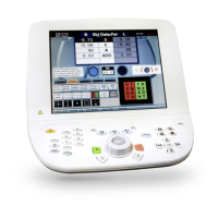
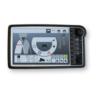
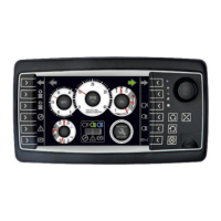
The core function of this system is to provide accurate rate control and section control for liquid applications. The Topcon Apollo CM-40 ECU acts as the master controller, capable of managing up to four application channels. For section control, the EM-24 Expansion Module integrates with the CM-40 ECU. This setup ensures that liquid products are applied only where needed, reducing waste and optimizing resource use. The system supports both Constant Flow and Hard Shut-off modes for section control. In Constant Flow mode, when a section valve is switched off, excess flow is diverted back to the tank, maintaining a consistent flow through the remaining open sections. This mode is recommended for better rate control. In Hard Shut-off mode, there is no return line to the tank, requiring the control system to reduce output from the pump module to maintain consistent flow to open sections. The system is compatible with Topcon X25, X35, XD+, and XD Consoles, providing a familiar interface for operators.
Before operation, the system requires a series of setup steps. Physically, the Liquid Systems (SA) Rate Control module, including tank plumbing, and a Stacker distribution system on the tool bar or planter must be installed. The Apollo CM-40 and EM-24 ECUs are then connected to the X Series Console using appropriate Topcon harnesses. Product tanks should be filled with water for initial testing.
The setup process within the console begins by creating a new implement profile with a liquid tank. The implement should be configured for both Section Control and Rate Control, specifying the ECU type as Apollo and the implement function as Seeder, utilizing both CM-40 and EM-24 ECUs. At least one liquid boom and one liquid tank need to be created. It's crucial to ensure the EM-24 is not connected to the CM-40 'comms' port during the initial detection of the CM-40. Once the CM-40 is detected, the EM-24 can be added and connected.
The EM-24's function must be set to "Section Control/Monitoring." For each liquid tank, the appropriate liquid type and drive (corresponding to the CM-40 port) must be selected.
Geometry setup involves selecting the implement and geometry, then choosing the boom for guidance. Measurements for the boom should be set according to the implement in use. Section control parameters are then configured, including the number of sections, section width, and the total number of liquid outlets (nozzles) for each section.
Timing settings allow for editing the on/off times for sections, starting with 0.1 seconds for each, which can be adjusted after testing. A virtual section switch can be enabled for on-screen manual override control of sections.
Tank setup involves editing tank parameters such as name, capacity, and assigning a pump source to the pump speed setting. Flowmeter setup requires entering the appropriate calibration factor based on the flowmeter type (e.g., TeeJet 801, ARAG Orion2). The "Balanced Valves" icon is used to select the section control mode (Enabled for Constant Flow, Disabled for Hard Shutoff).
Control valve setup involves configuring various parameters such as controller type (Regulator Valve), flow meter sampling (Standard), minimum and maximum on times, close valve when off (Enabled), reverse valve (Disabled), dump valve (Standard), controller mode (Standard or DICKEY-john depending on the module), gain setting, PWM setting, and pressure boost. Minimum and maximum on time, gain, and PWM settings can be adjusted later to fine-tune control.
Pressure sensor setup requires entering values for sensor type (Voltage), maximum pressure (10.00 bar), minimum voltage (0.00 V), and maximum voltage (5.00 V).
For displaying pump RPM on the run screen, a pump source needs to be configured in the Encoders Setup Page, matching the drive number for the liquid tank. If no pump source is available, an Auxiliary RPM Encoder can be set up, mapping it to the drive connected to the liquid tank. The Auxiliary RPM needs to be enabled on the General Inputs page, and a calibration factor (pulses/revolution) must be entered (36 for LQS70/120/180 module, 30 for LQS20 module).
The run screen can be customized to display pump speed by touching the data display area and selecting "Pump Speed" from the list of available parameters. Up to five parameters can be displayed. Similarly, Auxiliary RPM Speed can be enabled and displayed on the dashboard.
The manual outlines system setup verification tests to ensure correct operation. This involves starting the pump, selecting "Manual Speed" and a typical speed, choosing a pre-defined application rate, and using the "Virtual Master Switch" to initiate the test. Operators are encouraged to vary speed and application rate to confirm the control system performs correctly across the entire setup range. The "Virtual Master Switch" is used to terminate the test.
For instances where rate control is erratic, the operator can access the "Control Valve setup" screen to adjust control valve parameters. Decreasing the GAIN or PWM setting can lead to smoother control, while increasing these settings can provide faster response. Detailed information on these adjustments can be found in the Topcon Apollo Seeder Control Operator's Manual.
Section valve tuning is a critical maintenance step for correct liquid application in Constant Flow mode. This involves balancing the section valves while the module is running. The procedure includes starting the pump, performing a test with typical speed and application rates, ensuring all sections are open, and recording the indicated pressure on the section control module gauge. Then, section valve #1 is shut off via the control system, and the pressure change is observed. If pressure increases, the dial on the valve is rotated anti-clockwise until it drops to the previously recorded level. If pressure decreases, the dial is rotated clockwise until it increases to the recorded level. This process is repeated for all remaining valves, noting that sections with the same number of outlets typically require similar dial settings. This tuning ensures consistent flow and pressure across all active sections.
| Type | Controller |
|---|---|
| Model | CM-40 |
| Manufacturer | Topcon Liquid Systems |
| Input Voltage | 12 V DC |
| Output Voltage | 12 V DC |
| Application | Agricultural sprayer control |
| Features | Data Logging |
| Protection | Overload, Short Circuit |