WWW.NORAC.CA
PRECISIONDEFINED
Page9
Visitwww.solutions.norac.caformoresystem
installationandtroubleshootinginfo.
5.4. WingSensorInstallation
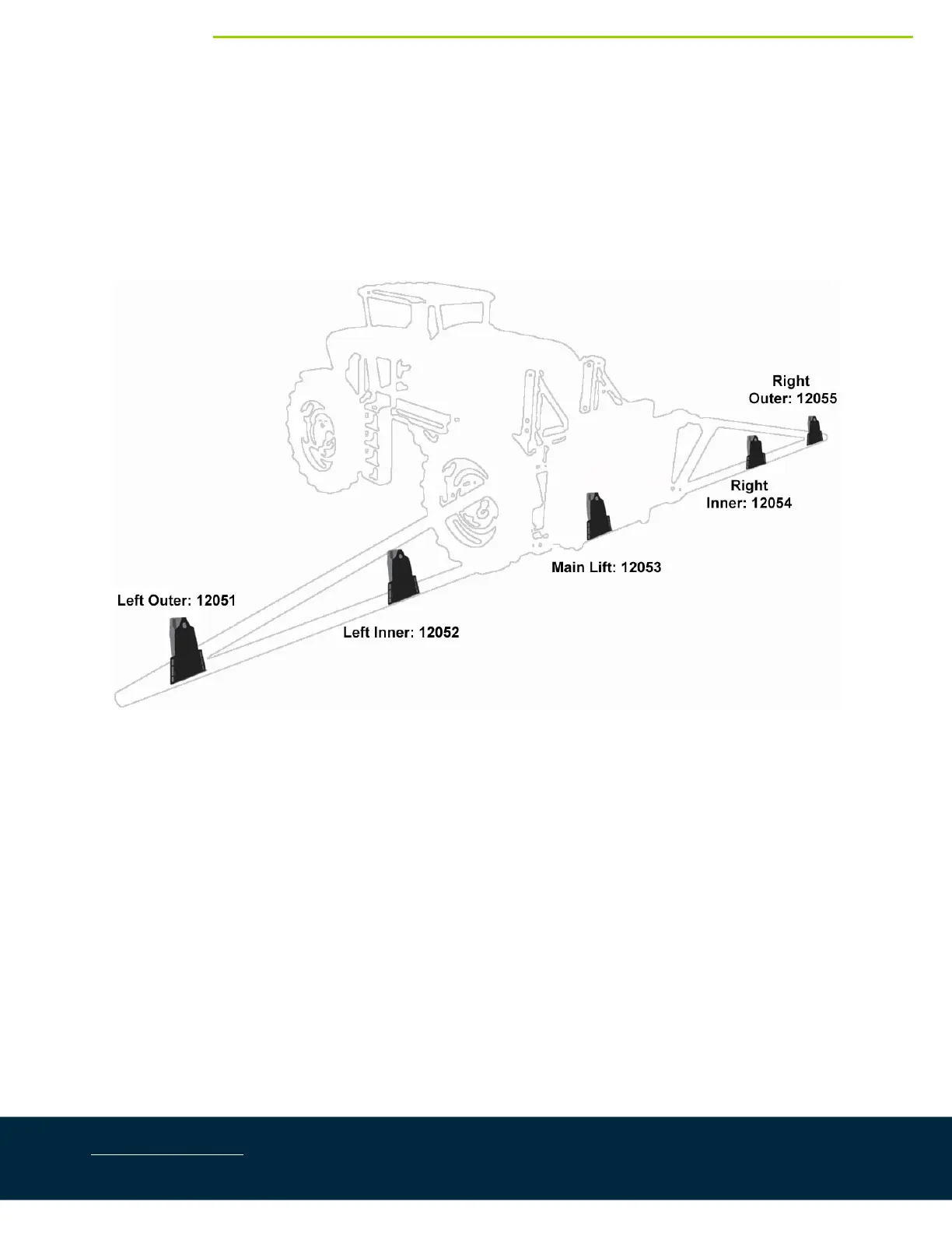
WheninstallingtheMAXSensors™(E07),startwiththesmallestserialnumberontheleft‐handside andproceed
tothelargestserialnumberontheright‐handside.Eachsensorhasaserialnumberstampedonthesensor
housing.
ApplyalightcoatingofthesuppliedPermatexAnti‐seizegreasetoallthreadedpartsuponinstallation.
Figure9:SensorSerialNumberArrangement
1. Thesensorbracketshouldbeorientedforward(aheadoftheboom).
2. Thebestmounting locationfortheouterwingsensorbracketswilltypicallybeneartheendoftheboom
tips,approximatelytwofeet(0.6m)fromtheend.
3. Mounttheinnerwingsensorbracketsontotheboomapproximatelyhalfwaybetweenthetipandcenter
ofthesprayerinsidethefirstfoldpoint.
4. MounttheMAXsensors(E07)intothesensorbrackets.TorquetheM8nutto108in‐lb(12Nm).Runthe
sensorcablethroughholeinthebackofthebracket.Ensurethecableisclearofmovingpartsandwillnot
bedamagedduringfolding.
5. ConnectcablesC05tothe8‐waycouplerandroutealongtheboom.
6. RoutecablesC05totheinnersensorbracket.Attheinnersensorbrackets,attacha3‐waycoupler(E10)
tothesprayerboom.ConnectcablesC05andthesensorcabletothe3‐waycoupler.ConnectcablesC05
tothe3‐waycoupler(E10)androutealongtheboomtotheouterwingsensors.
 Loading...