WWW.NORAC.CA
PRECISIONDEFINED
Page12
Visitwww.solutions.norac.caformoresystem
installationandtroubleshootinginfo.
6 ElectronicInstallation
6.1. HCM1Installation
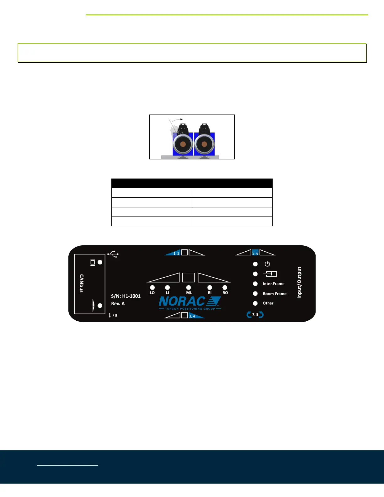
1. Verifythevalvecoil connectorsareorientedvertically(Figure15).Looseningthelargeplasticnutwillallow
theconnectortoberotated.
Figure15:AlignCoils
OutputNumber NormalFunction
1,2 LeftUpandDown
3,4 RightUpandDown
5,6 MainUpandDown
7,8 RollCWandCCW
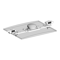
Figure16:HCM1Connections
Figure17:HCM1Label
2. PlacetheHCM1(E01)betweenthevalvecoils.Orientthe6‐pinDeutsch(CANbus)connectorstowardsthe
“P”and“T”portswiththelargelabelandLEDsfacingup.
3. SlidethemountingclipsovertheconnectorsoftheHCM1andthevalvecoilconnectors.Thismayrequire
flexingtheplasticbracketslightly.Ensuretheclipispushedovertheconnectorsfarenoughtoallowthe
clipstoengagebehindthevalveconnectors.