WWW.NORAC.CA
PRECISIONDEFINED
Page13
Visitwww.solutions.norac.caformoresystem
installationandtroubleshootinginfo.
6.2. SprayerInterfaceCa blingConnections
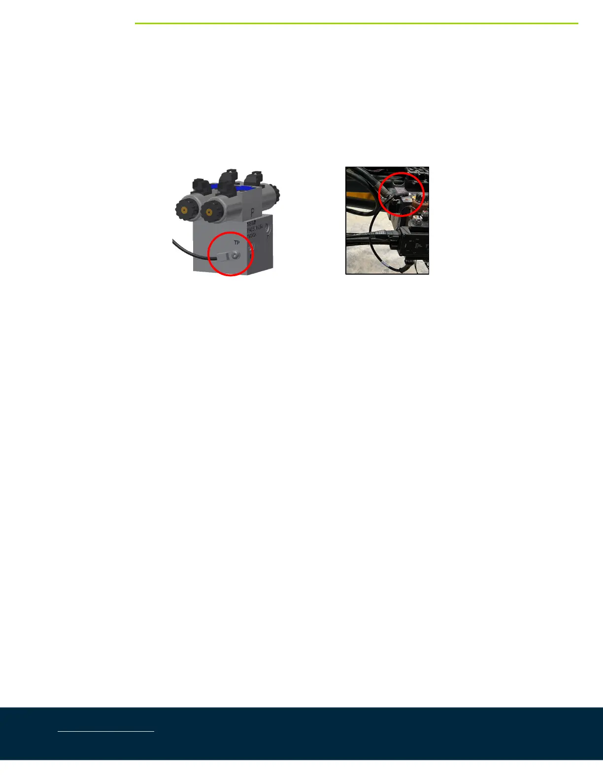
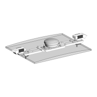
1. 3StationValveBlock:Connectthe temperatureprobe(C11–50120‐01)totheHCM1(temp/9connector).
Connectthetemperatureprobetotheholelabelled“TP”onthevalveblockusingthesupplied3/8”x1/2”
(9.5 mm x 25 mm) bolt (Figure 18).If the valve block does not
have a “TP” location, connect the new
temperatureprobetolocationwherethe previoustemperatureprobe wasinstalled.
Figure18:ValveBlockwithTemperatureProbeInstalled
2. 2StationValveBlock:Connectthe temperatureprobe(C12–50120‐02)totheHCM1(temp/9connector).
Connectthetemperatureprobetotheholelabelled“TP”onthevalveblockusingthesupplied3/8”x1/2”
(9.5 mm x 25 mm) bolt (Figure 18).If the valve block does not have a “TP” location, connect the new
temperature probe to location where the previous temperature probe was installed. Tee the 2‐pin
connectorsoncableC12tothemainliftlockingcoilontheHagievalveblock.
3. Connectthe4‐pinconnector labeled“Left”oncableC20totheHCM1connector1,2.Connectthe2‐pin
connectorlabeled“LeftUp”tothe leftboomliftconnectorontheTopconvalveblock.Connectthe2‐pin
connectorlabeled“LeftDown”totheleftboomlowerconnectorontheTopconvalveblock.
4. Connectthe4‐pinconnectorlabeled“Right”oncableC20totheHCM1connector3,4.Connectthe 2‐pin
connectorlabeled“RightUp”totherightboomliftconnectorontheTopconvalveblock.Connectthe2‐
pinconnectorlabeled“RightDown”totherightboomlowerconnectorontheTopconvalveblock.
5. 3StationValve Block:Connectthe4‐pinconnectorlabeled“Main”oncableC20totheHCM1connector
5,6.Connectthe2‐pinconnectorlabeled“MainUp”tothemainboomliftconnectorontheTopconvalve
block.Connectthe2‐pinconnectorlabeled“MainDown”to themainboomlowerconnectorontheTopcon
valveblock.
6. 2StationValveBlock:Connectthe4‐pinconnectoroncableC13totheHCM1connector5,6.Connectthe
2‐pinconnectorlabeled“OP1”tothemainboomliftconnectorontheTopconvalveblock.Connectthe2‐
pinconnectorlabeled“OP2”tothemainboomlowerconnectorontheTopconvalveblock.The“Main”
connectionsoncableC20arenotusedforinstallationswitha2stationvalveblock.Caporcovertheunused
connectorstopreventdustanddebrisfrominfiltratingtheharness.Ziptietheunusedconnectionssothat
theyareoutofthewayandwillnotinterferewiththemotionofthemachine.