WWW.NORAC.CA
PRECISIONDEFINED
Page14
Visitwww.solutions.norac.caformoresystem
installationandtroubleshootinginfo.
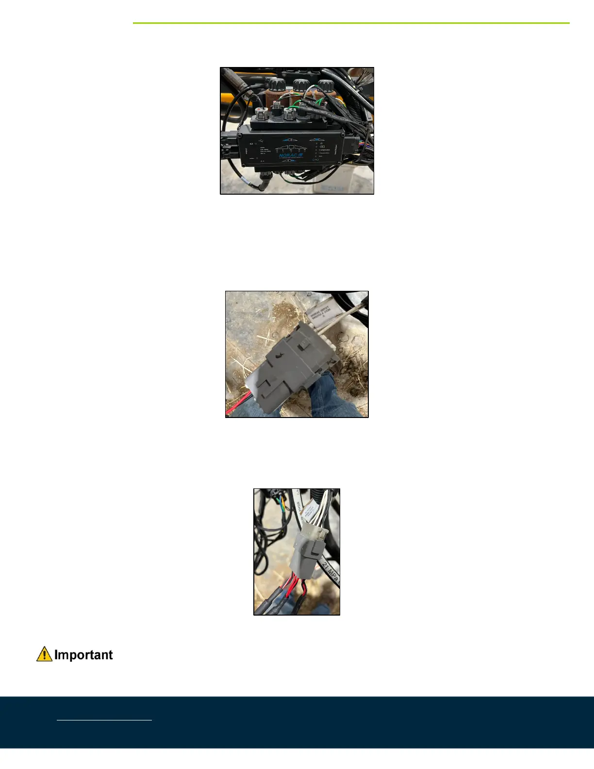
Figure19:HCM1MountedonValveBlock
7. Connectthe12‐pinplugconnectoroncableC20totheHCM1.
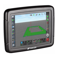
8. Connect the 12‐pin receptacle connector with two wires populated on cable C20 to the Hagie factory
connectionlabeled“NoracInputModuleOEM3”.
Figure20:NoracInputModuleOEM3Connection
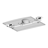
9. Connect the 12‐pin receptacle connector with all wires populated on cable C20 to the Hagie factory
connectionlabeled“ToNoracBoomSignalHarness”.
Figure21:ToNoracBoomSignalHarnessConnection
Ensurethatallunusedconnectorsarepluggedwiththeplugsprovided.