WWW.NORAC.CA
PRECISIONDEFINED
Page17
Visitwww.solutions.norac.caformoresystem
installationandtroubleshootinginfo.
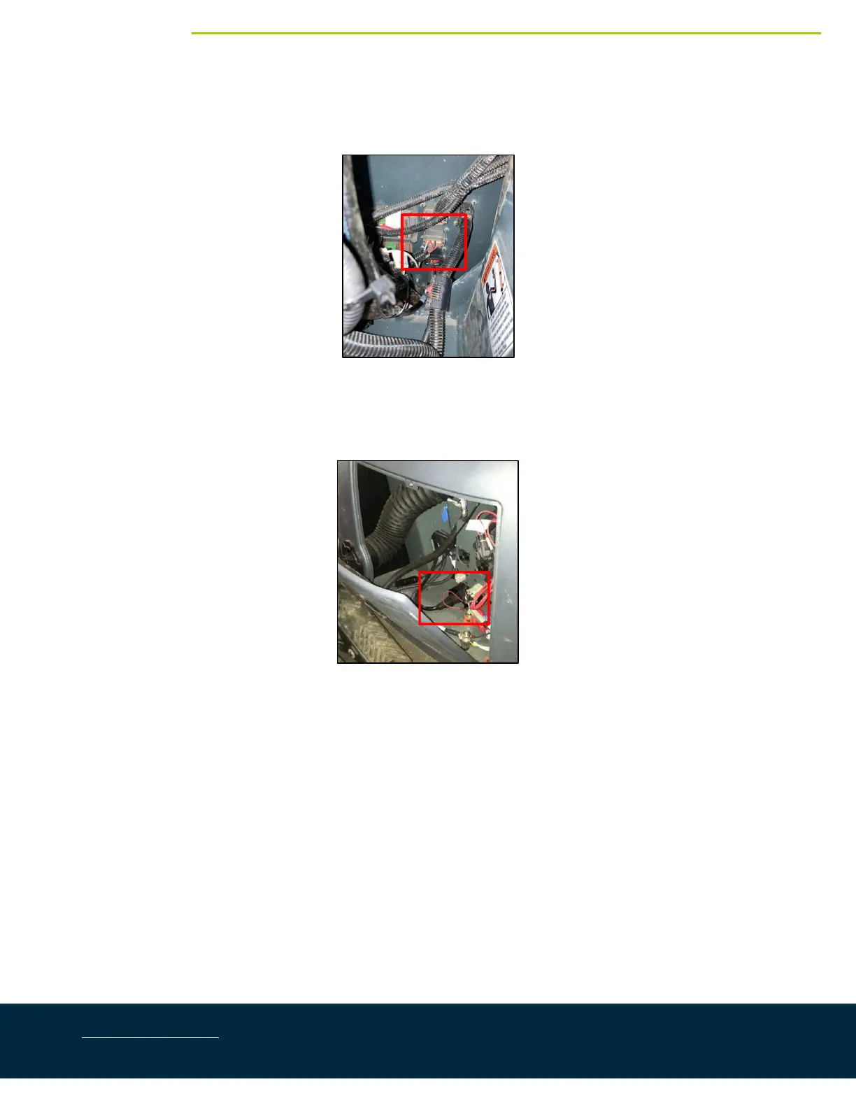
5. ConnectcableC03tocableC09witha2‐waycoupler(E12).Routethe12‐pinconnectorendunder the
bellyofthemachinetothe12‐pinbulkheadconnectorthatrunstothecab.
Figure26:BoomDisconnectCutout
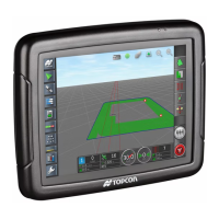
6. Mounta3‐waycoupler(E10) underthesideelectricalconsoleinthe cab(wherethe UC5ControlModule
wasremoved).
Figure27:BoomDisconnectCutout
7. Connect the existing harness from the 12‐pin bulkhead to the 3‐way coupler (E10). If this harness was
removed,installcableC01betweenthe12‐pinbulkheadandthe3‐waycoupler.
8. Connectthepowercable(C30)tothe3‐waycoupler.Connecttheoppositeendtothepowerconnection
undertheconsole.
9. ConnectcableC06tothe3‐waycoupler(E10).Connecttheoppositeendofcable C06toa2‐waycoupler
withterminator(E20).The2‐waycouplerwithterminatorisWHITE.
10. Connectthe2‐waycouplerwithterminator(E20)tothePulsedisplayorISO/UTconnection.