WWW.NORAC.CA
PRECISIONDEFINED
Page16
Visitwww.solutions.norac.caformoresystem
installationandtroubleshootinginfo.
6.4. DisplayCablingConnections
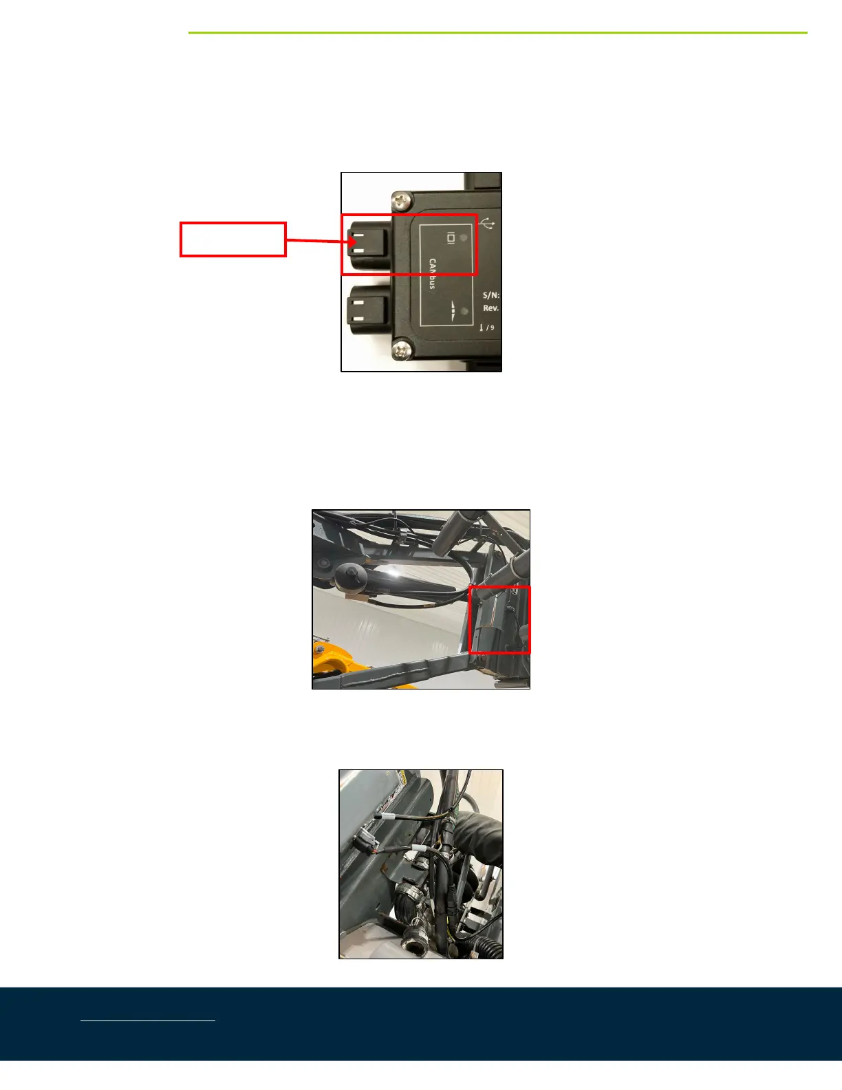
1. ConnectcableC02tothe6‐pindisplaybusconnectorontheHCM1(Figure23).
Figure23:DisplayBusLocation
2. Connect cable C02 to cable C04 with a 2‐way coupler with terminator (E20).The 2‐way coupler with
terminatorisWHITE.
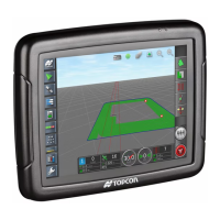
3. RoutecableC04uptotheright‐handsideoftheparallelliftarmstotheboomdisconnectcutout.
Figure24:BoomDisconnectCutout
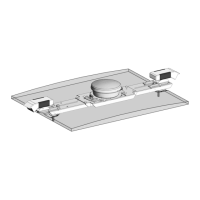
4. Connectthe12‐pinconnectoroncableC04tothe12‐pinconnectoroncableC09.
Figure25:BoomDisconnectCutout
DisplayBus