8
3
5
17
15
1x
12
1x
14
1x
1x
4x
2x
1x
19
1x
1x
1x
1x
7
2
9
6
4
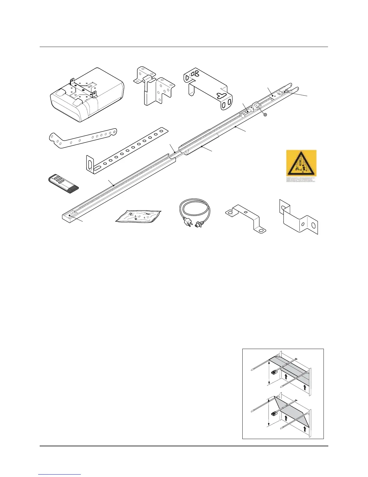
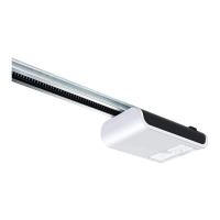
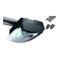
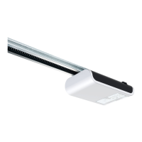
1. Drive head including LED module
2. Pinion*
3. Rail (model example) drive side*
4. Carriage*
5. Toothed belt or chain*
6. Deection roller*
7. Rail connector (model example)*
8. Rail (model example) door side*
9. Tensioner*
10. Wall bracket*
11. Door connector attachment
12. Linking bar
13. Central support
14. Bag of screws
15. Hand transmitter*
16. Ceiling mounting
17. Mains cable, 1.2 m length
18. Mounting bracket
19. Warning label
*Optional
Attention: Check the supplied screws and wall plugs to make sure that they are suitable for the structural
condition on the installation site.
Prepare the site for installation
1. The maximal distance between the drive head and wall socket is 1.2m.
2. Check the stability of the garage door. If necessary, tighten the screws and
nuts of the garage door.
3. Make sure that the garage door runs smoothly.
- Lubricate shafts and bearings.
- Check the pretension of the springs and adjust if necessary.
4. Establish the clearance at opening and closing of the garage door (h).
h
h