36 R-500/R-700
Installation
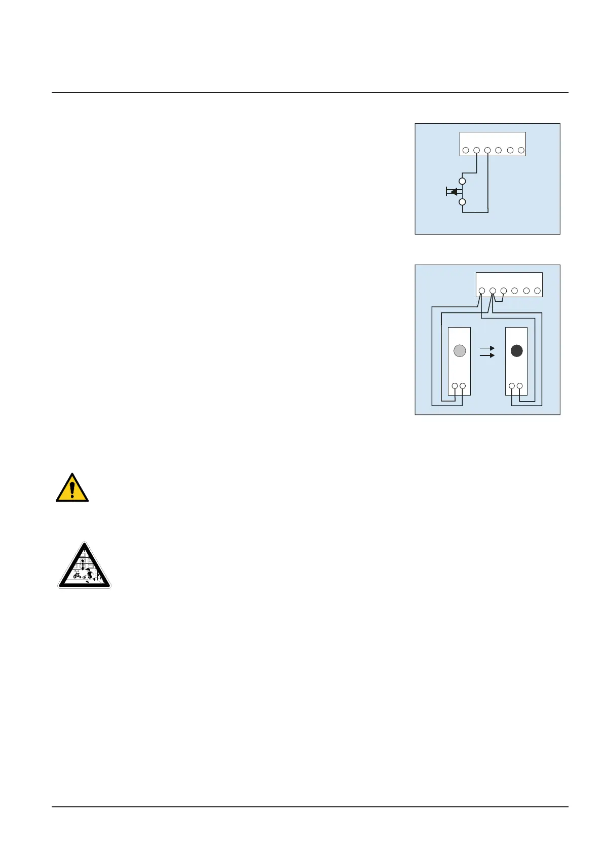
3. Input STOP A
The drive is stopped or the start-up is suppressed via this input.
G - Connection for slip contact (accessory) or emergency stop.
H G F E
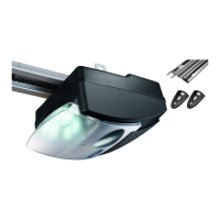
4. Input STOP B
G // H - Connection of photoelectric sensor LS2 (please refer to the
connection points of the photoelectric sensor manual for use of
other photoelectric sensors)
H G F E
1 2
LS 2
1 2
LS 2
1 2
LS 2
1 2
LS 2
1 2
Pulse generator and external safety devices
In situations of increased requirements in terms of personal protection, we recommend, in addition to
the internal power limitation of the drive, the installation of a photoelectric sensor. Further information
on our range of accessories can be found in our sales literature. Consult your specialist dealer.
Warning label
WARNUNG: Automatisches Tor - Nicht im Bewegungsbereich des
Tores aufhalten, da sich das Tor unerwartet in Bewegung setzen kann!
WARNING: Automatic door - The door may operate unexpectedly,
therefore do not allow anything/anyone to stay in the path of the door!
Place the sticker clearly visible on the inner surface of the garage door.
Dismantling the operator
1. Pull out the mains plug and disconnect all existing terminals.
2. Disconnect garage door and operator. Fix garage door.
3. Proceed according to the Installation instruction poster, but in reverse sequence.