EN-23T100 R
Menu 3 basic settings and initial operation
Setting the door end positions (menu items 30 and 31)
Please note that the upper and lower end position must be set
directly in succession. The end positions are approached in dead
man mode.
1. Select menu 3 "Basic settings" in the control and go to
menu item30 "Door setting of upper end position", so that
the number30 blinks on the display.
2. In order to define the upper end position, keep the but-
ton pressed until the door is completely open.
ð If the door moves in the wrong direction, a reversal of
the direction must be implemented. Keep the button
pressed for 5seconds and then repeat step2.
3. When the upper end position has been set, the lower end
position must be adjusted. Exit menu item 30 by pressing
the button once. The numeric point on the LED display
blinks 5times and in this way confirms the entry.
4. Switch to menu item 31 "Door setting of lower end posi-
tion".
5. In order to define the lower end position, keep the button
pressed until the door is completely closed.
6. Confirm the entry to complete the setting process.
NOTICE
The door must be spring balanced.
Depending on the driven the door must be spring
balanced.
WARNING
Crush hazard and risk of being struck by the
closing door
Ensure that no closing edge or photoelectric
sensor monitoring is active whilst the end posi-
tions are set.
Setting the 1/2 door opening (menu item32)
To set the position for a 1/2door opening, proceed as follows:
1. Select menu 3 "Basic settings" in the control and go to
menu item32 "Door setting 1/2 opening".
2. Press the button and keep it pressed until the door has
reached the desired position.
3. Confirm the entry to complete the setting process.
Fine adjustment of the door end position at the top (menu
item33) and at the bottom (menu item34)
1. Select menu 3 "Basic settings" in the control and go to
menu item33 "Fine correction upper end position".
ð The preset value50 blinks on the LED display.
2. Values 0 to 99 are provided to you for carrying out a fine
correction. Values of 50 (default setting) to 0 correspond to
0mm to approx. -80mm. Values from 50 to 99 correspond
to 0mm to approx. +80mm.
3. Confirm the entry and switch to menu item34 "Fine correc-
tion lower end position".
4. Values 0 to 99 are provided to you for carrying out a fine
correction. Values of 50 (default setting) to 0 correspond to
0mm to approx. -80mm. Values from 50 to 99 correspond
to 0mm to approx. +80mm.
Selection of closing edge J3 / selection of photoelectric
sensorJ4 (menu items35 and 36)
1. Select menu 3 "Basic settings" in the control and go to
menu item35 "Closing edge selection".
2. Select a value corresponding to the desired setting.
3. Confirm the entry and switch to menu item36 "Photoelec-
tric sensor selection".
4. Select a value corresponding to the desired setting.
5. Confirm the entry to complete the setting process.
Switch-off position of pre-limit switch (menu item37)
1. Select menu 3 "Basic settings" in the control and go to
menu item 37 "Correction of pre-limit switch closing edge
safety".
ð The preset value25 blinks on the LED display.
2. Set the switch-off position so that a maximum distance of
50mm to the ground contact is generated. Values between
0 and 99 are provided to you for this purpose. Values of 25
(default setting) to 0 correspond to 0 mm to approx.
-50mm. Values from 25 to 99 correspond to 0mm to ap-
prox. +100mm.
3. Confirm the entry to complete the setting process.
NOTICE
Compliance with standard EN12453
Check the switch-off position of the door after
every setting you have carried out. The switch-off
setting must correspond to a maximum distance
from the ground of 50mm, otherwise compliance
with the standard EN12453 is not ensured. This
might result in the loss of certification.
Menu 4 Further door settings
Duty cycle (menu item49)
The duty cycle set prevents the drive motor from being over-
heated and avoids damage.
NOTICE
Motor5.24 with a plastic gearbox
When motor5.24 with a plastic gearbox is used,
the duty cycle must be set to the value1 (3~) or
2 (WS,1~).
Menu5 Various settings
Smoke and heat extraction function (menu item55)
Select the corresponding door position in menu item55. Connect
the fire alarm system toJ7 and select the value10/11 in menu
item50.
Menu6 Radio settings
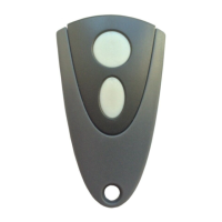
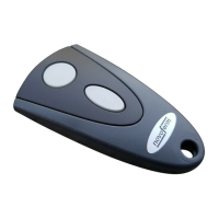
Programming the hand-held radio transmitter
Please observe that every hand-held transmitter must be pro-
grammed individually.
You are provided with the possibility of programming 30 radio
codes.
The following encryption types can be programmed: KeeLoq,
12 Bit Multibit. The first code programmed determines the encryp-
tion type.
 Loading...