52
Pre-Field Acceptance Test
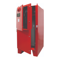
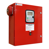
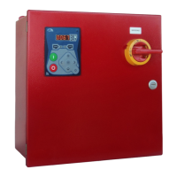
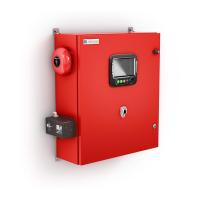
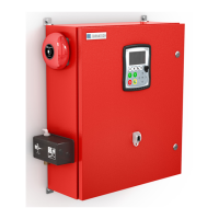
TORNATECH MODEL MPX
ELECTRIC FIRE PUMP CONTROLLER
PRE- FIELD ACCEPTANCE TEST
CHECK LIST
Note: This document should be an official indication of whether or not the installation and general condition
of the equipment is adequate for a field acceptance test. This document should also aid the individual
responsible for executing the field acceptance test to decide whether or not to carry out the field acceptance
test of the equipment.
Verify that the nameplate of the Fire Pump Controller corresponds with the AC voltage
available.
Visual inspection for any damage to the exterior of the Fire Pump Controller. Make sure
the enclosure, alarm bell, selector switch, membrane and display are not damaged.
Verify that the Fire Pump Controller has been installed within sight of the pump and engine
or motor.
Verify that the Fire Pump Controller has been installed not less than 12 inches from the
floor of the mechanical room.
Verify that all electrical connections to the Fire Pump Controller are done using liquid tight
conduit and connectors.
With the Fire Pump Controller door open, visually inspect for any drill chips, dirt or foreign
objects in the bottom of the enclosure, loose wires, broken components and general
proper electrician workmanship.
Verify that the correct Normal Power AC voltage is supplied to the controller by taking a
voltage reading at the incoming terminals of the isolating switch (IS).
Verify that the motor leads are connected for the corresponding starting method.
Start-up With TEST-NORMAL Selector Switch:
Make sure the Isolating Switch (IS) is in OFF position.
Verify TEST–NORMAL selector switch (SS1) is in NORMAL position.
Check electrical drawing for the external power source voltage (120v or 240v).
Connect the correct external power source to the plug.
Place TEST–NORMAL selector switch (SS1) in TEST position.
Verify LCD powers up with the following readings:
Time and Date: current time and date
Line Voltages: 0
Line Currents: 0
Cut-in, Cut-out, actual pressures
Push the START button, verify that the contactor 1M is closed.
Push the STOP button, verify that the contactor 1M is open.
Switch selector switch (SS1) to NORMAL position and unplug the power.
Initial Power-Up Check List:
Controller door must be closed and latched with Normal Power Disconnecting Means
handle in the OFF position. If a Transfer Switch is supplied, its door must be closed and
latched with the Alternate Power Isolating Switch handle in the OFF position.
Verify that the Emergency Start Handle is in the OFF position.
Verify that the Normal Power voltage and hertz displayed on the digital screen are the
same as measured in point 7 of the Installation Checklist above.
Verify that there is no Phase Reversal Alarm.
Note: A manual or automatic start must only be executed if the motor and the pump have
been cleared to be started by their respective official service technicians.
Place the Disconnecting Means handle in the ON position.
Push the START pushbutton. The motor will start.
Verify the motor rotation:
• If the motor rotation is correct, no adjustment is required.
• To correct the motor rotation, change motor connection leads 1 and 3 (A and C) at the
run contactor
Verify any alarms that would appear on the digital display screen. Correct any alarm