SteeringPositionSensor
g290696
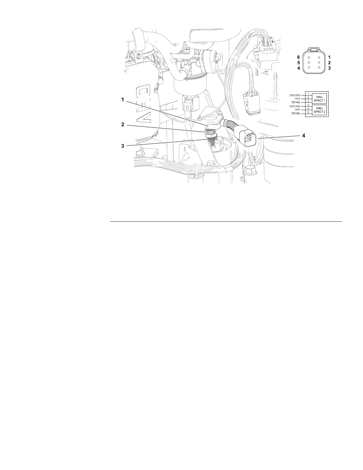
Figure81
1.Steeringpositionsensor
3.Casterforkshaft
2.Magneticbolt
4.Sensorharnessconnector
Thesteeringpositionsensorisatwo–pieceassemblylocatedontopoftherear
wheelcasterforkshaft.Thesensorportionincludes2analoghalleffectsensors.
Thesecondpieceoftheassemblyisaboltwithamagneticheadthreadedinto
thecasterforkshaft.Thesteeringpositionsensorfollowstherearcasterfork
movement.
Thesensoroperateson5VDCsuppliedbytheSC7:Steeringmotor.Signal
voltagefromthesteeringpositionsensor(alongwithinformationfromthe
steeringinputdevice)isusedbytheSC7:Steeringmotortodeterminethe
appropriatedirectionandcurrentowtooperatethesteeringmotor.Thesteering
positionsensorsignalsareconstantlymonitoredforsteeringfaultdetection.Ifa
steeringpositionsensorfaultoccurswhilethemachineismoving,themachine
willslowlycometoastop.Thebrakepedalcanbeusedtostopthemachine
soonerifnecessary.Asteeringsensorfaultwilldisablethetractionsystemuntil
theignitionkeyiscycledOFFandON.
TheInfoCenterDisplaycanbeusedtomonitorthedirectionofthesteering
positionsensorduringmachineoperation.
Note:Ifathesteeringpositionsensorisremovedforanyreason,thesteering
systemmustbecalibrated.Calibratethesteeringsystem–centerrst,then
calibratethesteeringsystem–range;refertoCalibratingtheSteeringSystem–
Center(page5–91)andCalibratingtheSteeringSystem–Range(page5–91).
TestingtheSteeringPositionSensor
Thesteeringpositionsensoranditscircuitwiringcanbetestedusingthe
InfoCenterDisplay;refertoUsingtheInfoCenterDisplayforTroubleshooting
(page3–39).Iftestingdeterminesthatthesensorandcircuitwiringarenot
functioningcorrectly,proceedwiththefollowingtestprocedure:
Greensmaster®eTriFlex3360and3370
Page5–89
ElectricalSystem:TestingtheElectricalComponents
19239SLRevB

 Loading...