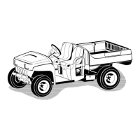
Figure41
1.Neutralbracket4.Wrong,musttightenthe
nut
2.Pullup
5.Correctadjustment
3.Cableboot
6.StarttheengineandshiftintoForward,Reverse,
andNeutralseveraltimestoensurethattheneutral
bracketisoperatingproperly.
InspectingtheTires
Checkthetireconditionatleastevery100hours
ofoperation.Operatingaccidents,suchashitting
curbs,candamageatireorrimandalsodisruptwheel
alignment,soinspecttireconditionafteranaccident.
Checkthewheelstoensurethattheyaremounted
securely.Torquethelugnutsto45-65ft-lb(61-88N-m).
AdjustingtheFront
Suspension
Therideheightofeachsideofthevehiclecanbe
adjustedseparately.Therideheightshouldbe8-3/4
to9-1/2inches(22.2to24cm)withthefollowing
parameters:
•Thetirepressureshouldbeat12psi(83kPa).
•Thevehicleshouldbedrivenbackandforthafew
timestorelaxtheA-arms.
•Measuretherideheightwiththewheelsfacing
straightaheadanda175-225lb(79-102kg)operator
inthedriver’sseat.
Note:Thedrivershoulddriveuptothe
measurementareaandstayseatedinthevehicle
whilethemeasurementisbeingtaken.
•Measuretherideheightonaatsurface,fromthe
bottomofthefronttonguetotheground.
1.Jackthefrontendofthevehicleoffoftheground;
refertoJackingtheVehicleinPremaintenance
Procedures,page27.
2.Removethetravellimitingbolt(Figure42).
3.LoosenthecenteringboltsinthefrontA-arm
(Figure42).
4.Removetherideheightadjustmentbolt(Figure42).
Figure42
1.Travellimitingbolt3.Rideheightadjustment
bolt
2.Centeringbolt
5.RotatethefrontA-armtothedesiredposition
(refertothenotebelow)andreplacetherideheight
adjustmentbolt(Figure42).
Note:TheA-armsaremadewithrubberandhave
differentspringrates.Becauseofthedifferentspring
rates,theA-armscomeadjustedfromthefactory
basedonthatspringrate.Generallytheadjustment
boltswillbeinstalledinholenumber2,3,or4
(Figure43)anditmaybedifferentfromtheleftside
(driverside)totherightside(passengerside).Ifthe
A-armslookliketheyaresagging,thentheyshould
beadjustedtothenexthighernumber(Figure43).
Eachholeequalsabout3/4inch(19mm)of
adjustmentatthewheel.Youwillalsoneedtodo
thisifyouareaddingheavyattachmentsorcarrying
heavyloadsoften.
34